Continue to Site

Welcome to EDAboard.com

Welcome to our site! EDAboard.com is an international Electronics Discussion Forum focused on EDA software, circuits, schematics, books, theory, papers, asic, pld, 8051, DSP, Network, RF, Analog Design, PCB, Service Manuals... and a whole lot more! To participate you need to register. Registration is free. Click here to register now.

3 Phase Induction Motor Driver Stage and Power Stage Design Help

Status
Not open for further replies.
I think that 600V rating of IRS2186 bootstrap drivers is too low for 400 V inverters. I'm not aware of other bootstrap drivers with sufficient voltage margin. That's why separate low- and high side drivers come into play.

Starting power electronics from the scratch means learning things the hard way. I smell burned burned IGBTs and drivers...
 

I would also strongly recommend being a distance away from your circuit. I have heard stories of engineers being quite badly injured and hospitalised by flying IGBT remnants. Are you hoping to design an industrial grade Inverter or is this a student project. I have posted elsewhere on this subject. Have a look in my posts for a thread 'Industrial grade inverter'. I to am concerned for your well being as you are exhibiting symptoms of inexperience.
 

@FvM

Ok. I too searched a lot for a good Vs High-Side Low-Side Driver but was not able to find it. I will revert back. I will use 6x HCNW3120 only.

I have a new question. It is regarding programming. I am using dsPIC33FJ32MC202 and mikroC PRO dsPIC Compiler. Crystal is 20 MHz. Project and Proteus file attached.

I am not getting the Signals.

When 6 channels mode is used does H and L signals will be complementary. It means that when PWM1Hx is high then PWM1Lx will be low. Does that also mean that there will be a 180 degree phase shift between the signals ?

6 signals are generated. Will the dsPIC auto generate 270 degree phase shifts between the PWM1Hx, PWM1H2 and PWM1H3 signals ? (also for PWM1L1, PWM1L2 and PWM1L3)

If the PWM1Hx and PWM1Lx doesn't have a phase shift of 180 degrees then should I implement it in the code ?
If the PWM1H1, PWMH2 and PWM1H3 signals doesn't have 270 degree phase shift then should I implement it in the code ?

I am using mikroC PRO dsPIC Compilers PWM_Motor Library.

Page 159 of dsPIC33 datasheet says it can be used for driving 3-Phase AC Induction Motor.

- - - Updated - - -

@brushhead

Why what is wrong with my latest circuit ? I am not using TLP250. I chose the right components. There will be a 10k Gate to Source resistor. A 22E gate series resistor for the IGBT. Somebody at Microchip forum had mentioned that is had used HCNW3120 opto-isolated driver for driving IGBTs for a 7.5 KW Induction Motor Driver.

Please see the attached image. I am not able to set the pair_output_mode and clock_prescale_output_postsclae parameters. Please explain it with an example. For now I just want to use PWM in 6 channel mode which are

PWM1H1
PWM1L1

PWM1H2
PWM1L2

PWM1H3
PWM1L3

Hx and Lx have to be complementary. I just want to see the 6 PWM signals on the scope.

This is the code I have written but I am not getting any signals.

Code:
PWM1_Mc_Init(10000, 1, 0x11, 0);
     PWM1_Mc_Set_Duty(32767, 1);
     PWM1_Mc_Start();

- - - Updated - - -

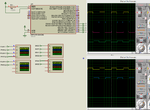
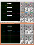
After experimenting a little with the PWM Library functions I made this code. I have a doubt with the bit value 0 / 1 which makes the Hx and Lx signals complementary. Please check the code and the image which shows the library function. See attached image which shows the signals. I am getting this signals. Are they correct.

Code:
pwm_duty = PWM1_Mc_Init(10000, 0, 0x77, 0);
     PWM1_Mc_Set_Duty(pwm_duty, 1);
     PWM1_Mc_Set_Duty(pwm_duty, 2);
     PWM1_Mc_Set_Duty(pwm_duty, 3);
     
     P1DTCON1 = 0xC3;  //Dead Time Register

     PWM1_Mc_Start();
 

Attachments

  • Three Phase AC Asynchronous Induction Motor Control.rar
    34.6 KB · Views: 77
  • PWM_Mc.png
    PWM_Mc.png
    144.8 KB · Views: 78
  • pwm 3 phase.png
    pwm 3 phase.png
    143.3 KB · Views: 87
Last edited:

@FvM

I am using dsPIC33FJ32MC202.

This is my code. Also the project and Proteus files are attached. Please have a look at the mikroC PRO dsPIC help file PWM_Motor Library and answer.

Am the 6 PWM signals correct ?

Code:
unsigned int pwm_duty = 0;

void main() {

     Delay_ms(200);

     ADPCFG = 0xFFFF;

     TRISA = 0x0000;
     TRISB = 0x0000;

     PORTA = 0x0000;
     PORTB = 0x0000;

     LATA = 0x0000;
     LATB = 0x0000;

     pwm_duty = PWM1_Mc_Init(10000, 0, 0x77, 0);
     PWM1_Mc_Set_Duty(pwm_duty, 1);
     PWM1_Mc_Set_Duty(pwm_duty, 2);
     PWM1_Mc_Set_Duty(pwm_duty, 3);
     
     P1DTCON1 = 0xC3;  //Dead Time Register

     PWM1_Mc_Start();

     while(1) {

     }
}

I am also referring this.

**broken link removed**

In section 7 it tells I need these signals.

Pwm1 – active high.
Pwm2 – active low and inverted of pwm1.
Pwm3 – active high and 120° phase shift of pwm1.
Pwm4 – active low and inverted of pwm3.
Pwm5 – active high and 240° phase shift of pwm1.
Pwm6 – active low and inverted of pwm5.

So, my 2nd question is

Should I convert these 6 PWMs to 6 SPWM and then shift the PWM1H2 120 degrees and PWM1H3 240 degrees w.r.t PWM1H1 ?
 

Attachments

  • Three Phase AC Asynchronous Induction Motor Control.rar
    21.4 KB · Views: 101
  • MC 6x PWM.png
    MC 6x PWM.png
    163.3 KB · Views: 73
Last edited:

I'm not using MikroC or Proteus and thus can't help with specific question.

There's apparently no sine carrier generation in your code snippets. You can hardly drive an AC motor without it.
 

@FvM

Why is a sine carrier needed ?

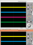
I am generating 3 pairs of 10 KHz PWM signals. These will be converted to six 10 KHz SPWMs. The Hx and Lx signals are complementary. In the image of the previous post I showed signals after zooming so that it shows that signals are comlementary and also the dead-band elimination. Here I am attaching the signals which show the 10 KHz PWMs.

Will not my method work.
 

Attachments

  • PWMs.png
    PWMs.png
    64.1 KB · Views: 68

Why is a sine carrier needed ?

Any AC motor (induction motor, synchronous motor, BLDC) must be driven with a low frequent (e.g. 50 Hz) multiphase voltage. Sine PWM is a method to generate it from a DC power supply.
 

@FvM

Can't I do without the Triangle wave ? I though I could implement the below method for the 6x SPWMs and using SET_FREQ I would adjust the AC frequency.

https://tahmidmc.blogspot.in/2013/02/demystifying-use-of-table-pointer-in.html

I have implemented this in PIC and it works. I am trying to implement thamid's method in dsPIC33. I also have to implement V/F control. I am thinking about using the ADC for it. The output AC voltage is scaled and converted to 5V DC range and fed to ADC. Based on ADC value SET_FREQ (used in thamid's method) is calculated and used to maintain constant V/F. Will this work ?

- - - Updated - - -

Thamid's method

SET_FREQ = 2^16/(Number of sine table values * Number of times each value is to be called)

My PWM Freq = 10 KHz

P = 1/T = 100us

Timer2 is configured for 100 us

SET_FREQ = 65536 / (1024 * 1) (1 assumed)

= 64

Number of times each value is to be called = 1 and so TBL_POINTER_NEW[x] has to be shifted 6 times to right
because sifting a 16 bit number 6 times to right gives a 10 bit number. This 10 bit number (0 - 1023) is used a

index for the sine table.

P = 100us

P * no. of points = 100 us * 1024 = 102.4ms (for 180 degrees because sine table is for 180 degrees)

So, AC freq = 1/F = 1/(102.4m * 2)= 4.8828125 Hz

Is this calculation correct ?


Lets take no. of points = 100

so, for 10 KHz PWM

100 us * 100 = 10 ms

F = 1/10m * 2 = 50 Hz

SET_FREQ = 65536 / (100 * 5) (5 assumed)

= 131.072

I have taken 100 points in 180 degrees of Sine Wave and so 100 is a 8 bit value and so I am shifting

TBL_POINTER_NEW[x] 8 times to right. which leaves a 8 bit value.

So, if I need a 15 to 50 Hz variable frequency sine wave from the SPWM then I only have to vary the no. of

times each sine table entry is repeated.

I have implemented this in dsPIC33 for PWM1H1 and PWM1L1 but I am not getting the sine wave.
 

@FvM

If I add a 10 KHz SPWM and 50 Hz Triangular wave do I get a 50 Hz Sine wave ?
 

You don't use triangle waves in digital PWM generation. You have a 10 kHz triangle in an analog PWM generator.

The sine phase is increasing continuously from 0 to 360 degree and jumps back to 0, forming a 50 Hz (or whatever the actual output frequency is) sawtooth wave. A three phase inverter has three 120 degree phase shifted saw tooth waves.
 

I will use Thamids method for the three phases.

https://tahmidmc.blogspot.in/2013/02/demystifying-use-of-table-pointer-in.html

I will use dsPIC33 which generates 3 and 3 Complementary PWMs. By using Tahmid's method I will generate 3 sine waves first after that I will shift the other two SPWMs by 120 and 240 degrees w.r.t first sine wave. I will just use three different duties loaded to the three PWM channels. This will give the 3 Phase Sine Waves.

I will test this and reply.

I earlier mentioned that I will use HCNW3120 for driving the IGBTs for the 7.5KW Induction motor Driver.

Why can't I use IR2110. See in the attached application note page no. 26 it shows IR2110 used for a 3 Phase Induction motor Driver. Can I use it ?
 

Attachments

  • an-978.pdf
    425.2 KB · Views: 82

Status
Not open for further replies.

Part and Inventory Search

Welcome to EDABoard.com

Sponsor

Back
Top