Continue to Site

Welcome to EDAboard.com

Welcome to our site! EDAboard.com is an international Electronics Discussion Forum focused on EDA software, circuits, schematics, books, theory, papers, asic, pld, 8051, DSP, Network, RF, Analog Design, PCB, Service Manuals... and a whole lot more! To participate you need to register. Registration is free. Click here to register now.

16 relay module

AboudaKing

Member level 1
Joined
May 22, 2019
Messages
37
Helped
0
Reputation
0
Reaction score
1
Trophy points
8
Activity points
234
hello.
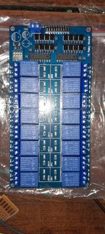
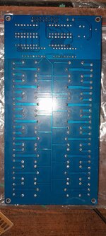
i have recently bought a 16 relay module from Aliexpress, i tried to test it now but it's not powering on, and i just have noticed it's not similar to the ones i seen before, looks like its missing few parts 'not soldered'
i have googled it and seen other modules same as mine
does the module without those pieces supposed to work 'considering they are selling it this way multiple places'
if not what are the reference to those parts so i can fix it
thank you
71s3CRHGzL._AC_SL1500_.jpg

1695673991494.png
 
Hi,

looks like there is a switched-mode power supply missing, most likely a buck-converter. U19 is might be some kind of "Simple-Switcher" (Texas Instruments), which incorporates the switch. I assume you have tried to power up the boad with 5 V connecting to Vcc? From the top side it seems there is no connection between Vcc and the zero Ohm resistor R18 (output of the buck-converter?). So if there is no connection on the bottom side, your electronics will not be powered. Please use a multimeter to check if a connection between Vcc and R18 exist, and also between Vcc and the supply pins of the ICs as well between the R18 and the supply pins. Depending on your measurment results, you may create a connection by means of a wire between Vcc and R18, but check the maximum voltage rating of the components on the board as well.

BR
 
Those look like electrolytic capacitors, often used in power supplies. Possibly the manufacturer sent out the boards 'as is' because he didn't have the power supply. Or maybe his power supply is suited only for a few regions.

The relay coils are labelled for 5V. Each coil probably needs a watt to operate. Do you have a 5VDC 16W power supply? I think your board will work if you hook up your own power supply.
 
As i tested the missing conection is the GND,relays,ic's,optocoplers all worrks fine
Connection is valid in the + side of the missing componants and ic's but GND is missing
Hi,

looks like there is a switched-mode power supply missing, most likely a buck-converter. U19 is might be some kind of "Simple-Switcher" (Texas Instruments), which incorporates the switch. I assume you have tried to power up the boad with 5 V connecting to Vcc? From the top side it seems there is no connection between Vcc and the zero Ohm resistor R18 (output of the buck-converter?). So if there is no connection on the bottom side, your electronics will not be powered. Please use a multimeter to check if a connection between Vcc and R18 exist, and also between Vcc and the supply pins of the ICs as well between the R18 and the supply pins. Depending on your measurment results, you may create a connection by means of a wire between Vcc and R18, but check the maximum voltage rating of the components on the board as
--- Updated ---

I tested the board with 5v 5W power supply all the relays works fine 'ddnt activate them together' relay needs like 90mah .


Those look like electrolytic capacitors, often used in power supplies. Possibly the manufacturer sent out the boards 'as is' because he didn't have the power supply. Or maybe his power supply is suited only for a few regions.

The relay coils are labelled for 5V. Each coil probably needs a watt to operate. Do you have a 5VDC 16W power supply? I think your board will work if you hook up your own power supply.
 
Just a caution - without seeing the underside I can't be sure about that particular board, some of the boards like that claim to be opto-isolated relay drivers but the inputs all share a common ground. In other words there is no advantage to using the optocoupler, the board cannot be used as independent relay channels.

When all the inputs are driven from the same source they work equally well if you remove the opto-couplers and replace them with a wire link so it then operates from standard logic level inputs.

Brian.
 
As i tested again
VCC is connected to everything
GND is not connected to optoplers and the entire regulator place is grounded and 'L1' have no connection to GND


Just a caution - without seeing the underside I can't be sure about that particular board, some of the boards like that claim to be opto-isolated relay drivers but the inputs all share a common ground. In other words there is no advantage to using the optocoupler, the board cannot be used as independent relay channels.

When all the inputs are driven from the same source they work equally well if you remove the opto-couplers and replace them with a wire link so it then operates from standard logic level inputs.

Brian.
--- Updated ---

Buttom side
 

Attachments

  • 20230926_131015.jpg
    20230926_131015.jpg
    1.7 MB · Views: 71
  • 20230926_131026.jpg
    20230926_131026.jpg
    1.2 MB · Views: 63
As I suspected, all the optocouplers are linked together. These boards would be far more versatile if both pins on the LED side were individually wired to the header. For no extra cost it would give you 16 independent and isolated channels.

Brian.
 
As I suspected, all the optocouplers are linked together. These boards would be far more versatile if both pins on the LED side were individually wired to the header. For no extra cost it would give you 16 independent and isolated channels.

Brian.

Now if solder wires to connect GND to 'L1' (the missing part) tht should fix it ?
Or any other solution to fix this boared
 
It should work as it is. The screw terminals are for voltages higher than 5V, typically 12V in which case the regulator components have to be fitted to drop it down to 5V. If you apply 5V where marked on the pin connector the regulator components are not needed.

5V is fed to all the opto-isolators, there is no ground on them because you provide the ground connection through the pin connector to turn the relays on. To operate the relays you link the input pin to ground or at least drive it to a logic low level, that lights the LED in the optocoupler and that operates the IC which is a relay driver.

Brian.
yes that's how it worked eventually, they should have pointed that in description
thank you
 

LaTeX Commands Quick-Menu:

Part and Inventory Search

Welcome to EDABoard.com

Sponsor

Back
Top