Continue to Site

Welcome to EDAboard.com

Welcome to our site! EDAboard.com is an international Electronics Discussion Forum focused on EDA software, circuits, schematics, books, theory, papers, asic, pld, 8051, DSP, Network, RF, Analog Design, PCB, Service Manuals... and a whole lot more! To participate you need to register. Registration is free. Click here to register now.

12vdc to 230 vac inverter freewheeling diode burning.

Status
Not open for further replies.

myfaithnka

Advanced Member level 4
Joined
Nov 5, 2010
Messages
106
Helped
2
Reputation
4
Reaction score
2
Trophy points
1,298
Activity points
2,022
Hi all,
I am trying to make a home made inverter.
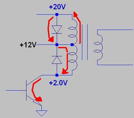
I am referring driver side of this schematic
PWM-inverter-circuit.png

I replaced 2n6277 with two 2n3773 (parallel).

My problem is that the free wheeling diodes I used are getting burned out every time,I removed them and the circuit is working,but I am not using the circuit without freewheeling diodes as that may kill the transistors due to inductor spikes.
I am using a 20w CFL as secondary load.

Can any one tell me whats happening,how can i solve this.

Please help.

Thanks.
 

Make sure that the free wheeling diodes are able to carry the current flowing.
Why not change to MOSFETs?
 
Freewheeling diodes are shorting the transformer output voltage, just an erroneous design. Think how a transformer works.

It may me useful to connect Z-diode + rectifier combinations or bidirectional TVS diodes across the primary windings to limit overvoltage peaks created by the transformer leakage inductance. But it's breakdown voltage must be above supply voltage.
 
It seems your Diodes are not able to carry the current. 1N5408 is not a fast type, and BA 159 has low forward current.

- - - Updated - - -

Isn't it depend on the kind of the winding. if it's a EI type transformer, and primary winding is just a winding with a middle connection I am agree with FvM.
 
Make sure that the free wheeling diodes are able to carry the current flowing.
Why not change to MOSFETs?

I Tried mosfets like irfz44n first,they breaks like crackers.

- - - Updated - - -

It seems your Diodes are not able to carry the current. 1N5408 is not a fast type, and BA 159 has low forward current.

- - - Updated - - -

Isn't it depend on the kind of the winding. if it's a EI type transformer, and primary winding is just a winding with a middle connection I am agree with FvM.

i took out an tfr from old ups.

- - - Updated - - -

hi all,
what do you say if i place diodes across transistor ?
are this diodes really needed ?
is there alternate strategies ?

thanks
 

Find a new irfz44n MOSFET, remove the output of SG3524 ic and ground the gate of the two MOSFETs and power the inverter. Then give me a feedback, I am suspecting that the two sides are at one time being switched ON the same time.
 
could you show me the current passes through the diode?
just for finding the reason of the failure, add a 15 ohm resistor in series with diode, and report the result.
 
Hi,

FvM is right
Read post#5.
Only one small thing is that i expect 22V instead of 20V.

Onother thing is your output stage. Are you sure to connect the capacitors directely to the transformer output...without a series inductor?
I expect high current peak on the 12V side and through the capacitors but about no benefit in output voltage waveform.

Klaus
 
Only one small thing is that i expect 22V instead of 20V.
You are of course right.

Scary to see so many contributions in this thread ignoring the obvious and discussing minor aspects...
 
If the transformer is well designed, the coupling between the two halves of the primary will be very tight, so as explained when one end is "earthed" the other end will swing to 2 X Vcc. The only problem will be the leakage inductance which will generate an EMF = Di/Dt X L. So there will be a short high voltage pulse which needs to be suppressed. As the level and duration of this pulse is dependent on the transformer's leakage inductance it is not easily calculated. Feed the output stage from a variable supply, reduce it to zero. Remove your diodes. monitor the end of the transformer with a CRO. Set the inverter going and gradually increase the voltage to the output stage. Look out for the high voltage ring at the start of the voltage. See how bad it is and if present and of a high amplitude when the Vcc is 12V. Try putting a snubbing network (1 ohm +.01MF in series) across the transformer.Select the components for maximum risetime with minimum over voltage.
Frank
 
Last edited:
Hi all,

I will surely reply to all of you,but I am hospitalized for a leg injury, please be patient.

please give me week to recover.

thanks and regards,

nithin
 

Find a new irfz44n MOSFET, remove the output of SG3524 ic and ground the gate of the two MOSFETs and power the inverter. Then give me a feedback, I am suspecting that the two sides are at one time being switched ON the same time.

You are right,I forgot to tell this, after the mosfet breaking incident, I removed the TFR and connected two 55w 12v Automobile head lights,then brought the frequency down to see the bulbs lighting up one after one,I found leakage in one half cycle,so I added 1K resistors grounded at the IC outputs pins, then I got no more mosfets left but only transistors. Now I am sure there is no simultaneous switching on of both transistors.

- - - Updated - - -

Hi,

FvM is right
Read post#5.
Only one small thing is that i expect 22V instead of 20V.

Onother thing is your output stage. Are you sure to connect the capacitors directely to the transformer output...without a series inductor?
I expect high current peak on the 12V side and through the capacitors but about no benefit in output voltage waveform.

Klaus

hello klaus,
I am not an experienced hobbyist,I make many mistakes.
please tell me more, are the capacitors in secondary problematic ?
they are told to be giving the waveform smooth shape,again I am not sure about that. please tell me more about it.

nithin

- - - Updated - - -

If the transformer is well designed, the coupling between the two halves of the primary will be very tight, so as explained when one end is "earthed" the other end will swing to 2 X Vcc. The only problem will be the leakage inductance which will generate an EMF = Di/Dt X L. So there will be a short high voltage pulse which needs to be suppressed. As the level and duration of this pulse is dependent on the transformer's leakage inductance it is not easily calculated. Feed the output stage from a variable supply, reduce it to zero. Remove your diodes. monitor the end of the transformer with a CRO. Set the inverter going and gradually increase the voltage to the output stage. Look out for the high voltage ring at the start of the voltage. See how bad it is and if present and of a high amplitude when the Vcc is 12V. Try putting a snubbing network (1 ohm +.01MF in series) across the transformer.Select the components for maximum risetime with minimum over voltage.
Frank

hello frank,

being in hospital bed gives me time for many insights, are you suggesting me to go for a snubber network instead of these diodes? I just googled the word,which is a new idea for me, I saw many inverter schematics with RC Snubber networks. what do you say ?

- - - Updated - - -

The problem is about understanding transformer operation in push-pull output stage

7495771900_1409522977.jpg

hello,

This is a new idea for me, so forgive my ignorance if I am asking anything foolish,
are these back emf voltages actually getting applied across that diode without any load but the total diode resistance ?
can this be solved by adding rc elements in the loop ?

thank you for your time,i really appreciate it.
 

This is a new idea for me, so forgive my ignorance if I am asking anything foolish,
are these back emf voltages actually getting applied across that diode without any load but the total diode resistance ?
can this be solved by adding rc elements in the loop ?

I believe that you added the diodes to cut "back EMF" as you do with a relay coil or solenoid valve. But this is a transformer and when one transistor is switched on, the voltage across the other transistor will (hopefully) raise to double the battery voltage.

Due to the less than perfect windings coupling, you get a voltage peak above this 2*Vbat level when a transistor is switched off. I think that zener diode + rectifier combinations or bipolar voltage limiting diodes are better suited to cut these overvoltage peaks than RC snubbers. But a RC snubber as suggested by chuckey can work too.
 

Hi,

Read about LC filters.

With switching signals you get very high voltage rise. Capacitors are low ohmic for high voltage rise. High current is the consequence. You need a device to become high ohmic with high voltage rise, these are inductivities. Capacitors and inductivities combine to a low pass filter, reducing overtones and making signal smooth and sinusoid.

Klaus

yes now understand,so where should I add an inductor in series ?
 

Hi,

yes now understand,so where should I add an inductor in series ?

Directely at the output, In series to your Cs.

Klaus
 
Status
Not open for further replies.

Similar threads

Part and Inventory Search

Welcome to EDABoard.com

Sponsor

Back
Top