Continue to Site

Welcome to EDAboard.com

Welcome to our site! EDAboard.com is an international Electronics Discussion Forum focused on EDA software, circuits, schematics, books, theory, papers, asic, pld, 8051, DSP, Network, RF, Analog Design, PCB, Service Manuals... and a whole lot more! To participate you need to register. Registration is free. Click here to register now.

12VDC-220VAC pure sine inverter using SG3524 and IR2110

Status
Not open for further replies.
Brian,
I did read with a lot of interest those posts.
I think you can give me some directions to build an home made PV battery charger using the MPPT function.
There is a lot of " words " on the web but I can not find a complete system.
I saw Microchip project in the relevant application note but the schematics diagram drawing has some missing connection.
My system will charge a 12 Vdc lead acid battery an the pv is about 100 w.

Thanks for any help
Regards,
Ambrogio
IW2FVO
North Italy


I would suggest you visit the Microchip web site, most PIC devices have PWM generators in them as standard. I think my first choice would be the PIC18F1320 because it is very low cost and already has a four-phase PWM generator built in to it. This means you can produce the drive signal to all the FETs (using IR2110 to shift the voltage levels) directly by setting some values in PIC registers. It will allow you to produce any on/off ratio between 0% and 100%, all you have to do is produce the sine wave in software or use a look-up table of sine levels then send them to the PWM register in time to modulate at the right frequency. The PIC also has several ADC channels which you can use to stabilize the output or monitor the load.

The data sheet and free assembler are at Microchip Technology Inc. is a Leading Provider of Microcontroller and Analog Semiconductors, providing low-risk product development, lower total system cost and faster time to market for thousands of diverse customer applications worldwide. where you will also find trial versions of 'C' compilers which should be adequate to complete this task without having to buy a full version.

Incidentally, I am using a similar PIC to generate speech using PWM so low frequency power AC signals should be no problem!

Brian.
 

You are re-opening an old thread.

You might be able to use an SG3524 to generate a sine wave but it isn't intended to be used that way.
That device is intended for normal SMPS designs where the intention is to produce a stable DC output. It might be possible to modulate it's reference input to make a sine output but as stated before, a H-Bridge PWM system will be simpler and more efficient.

Brian.
 
Brian ,
I am still searching for a complete project for a sine wave inverter.
Is there any real available "complete" project ?
Thanks
regards,
Ambrogio

You are re-opening an old thread.

You might be able to use an SG3524 to generate a sine wave but it isn't intended to be used that way.
That device is intended for normal SMPS designs where the intention is to produce a stable DC output. It might be possible to modulate it's reference input to make a sine output but as stated before, a H-Bridge PWM system will be simpler and more efficient.

Brian.
 

Last edited by a moderator:

You might also look at chips meant for Class D audio (but you
won't, I expect, because this is a dictated project). These
most likely support bridging, may be able to drive power FETs
up to a decent gate charge, and would have no problem
following a 50/60Hz sine reference. They also tend to be
aimed at 12V input, car audio apps.
 
  • Like
Reactions: IW2FVO

    IW2FVO

    Points: 2
    Helpful Answer Positive Rating
dselec - making sine waves out of square waves is extremely inefficient. You would lose much of the output power in heating the filters and still not have a clean sine wave at the output.

Ambrogio, if you Google for sine wave inverters you will find many designs using PWM, it is the standard way of doing it these days. The SG3524 is not a sine generator though and I would forget using it for this application. It has two outputs that are designed to drive the output stage at switching frequency. In PWM you drive at a much higher frequency than the sine wave you want, then modulate the pulse width at 50/60Hz to control the relative on and off times of the output stage.

The only time you might use an SG3524 is in a DC-DC converter to generate a high voltage supply to feed a PWM stage but in that situation, a different device is also used to generate the PWM signals themselves. For example you might use it to convert 12V DC into 300V DC then use a PWM controller to convert the 300V DC into a 220V sine wave.

Brian.
(aka GW6BWX)
 

Thanks for the reply,
Ambrogio

---------- Post added at 18:12 ---------- Previous post was at 18:10 ----------

Thanks,
do you have a complete project for the class d audio amplifier sine wave inverter ?
Thanks
Ambrogio

---------- Post added at 18:14 ---------- Previous post was at 18:12 ----------

Brian
any link for me '
Thanks
Ambrogio
 

Brian,
it tells to me : file not found ( error 404 ).
Ambrogio
 

but the circuit shown in the link **broken link removed** is completely made of ic's... it's a bit difficult to make... i have heard that there is another method to do this...ie. first converting the low voltage DC to low voltage AC and then using a transformer to step up the low AC voltage to high (230V) ac... can i get that circuit?
 

Again,
this liink gives me error 404 ( file not found ! )
Ambrogio


but the circuit shown in the link **broken link removed** is completely made of ic's... it's a bit difficult to make... i have heard that there is another method to do this...ie. first converting the low voltage DC to low voltage AC and then using a transformer to step up the low AC voltage to high (230V) ac... can i get that circuit?
 

Hello Mr.deselec,
I am surprised to note your suggestion regading getting 12v dc into squre wave and then filtering the same one can get sine wave.how it is possible,hve you some cct to simulate please because i think it is not possible.
 

Thanks Tahmid, that's the same document, the opriginal link has been removed.

Generating low voltage AC then using a transformer to step it up is possible but inefficient. The trouble is you need very high primary currents and the resistive loss in the wire becomes significant. Also the power driving stage has to carry that power and linear high current amplifiers, especially driving inductive loads are not easy to build.

PWM generates the AC waveform directly from a DC source so no output transformer is needed.

Brian.
 

Hello my friend did you get through with your inverter using sg3524
 

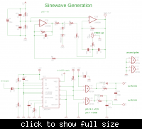
I have already posted this thread to the Power Electronics section. But I cant find a way to send you the schematic diagrams without showing it to everybody else. So I decide to show it here. This circuit below is suppose to be connected to a MOSFET fullbridge via IR2110. But as it turned out, it doesn't work as intended, so please tell me how should I make it work.


Please note some main keys as follow

1. Your sine-pwm signal is full wave modulation so your load should connect to Vcc/2 to get actual sine current(Pos and Neg)
2. Adjust R12(2k2) to get a 50% pulse-width when no sine signal apply to C8
3. This circuit can not use with H-Bridge because you have no detection Pos or Neg cycle, the modulation method can not apply to H-Bridge
 
I sincerely appreciate your design. i will try it and feed you back. i used similar cct , mine is a modified sine wave(SG3524 +2 of IR210) i will attach the pcb format which can view with expresspcb.
 

Status
Not open for further replies.

Part and Inventory Search

Welcome to EDABoard.com

Sponsor

Back
Top