Continue to Site

Welcome to EDAboard.com

Welcome to our site! EDAboard.com is an international Electronics Discussion Forum focused on EDA software, circuits, schematics, books, theory, papers, asic, pld, 8051, DSP, Network, RF, Analog Design, PCB, Service Manuals... and a whole lot more! To participate you need to register. Registration is free. Click here to register now.

12v dc to 220v ac inverter,how can we convert it into ups?

Status
Not open for further replies.
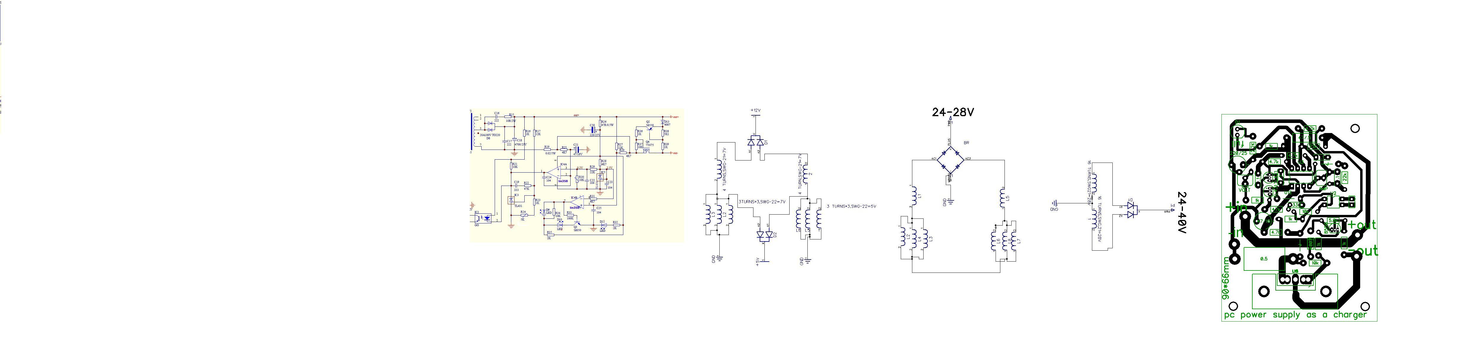
Increasing 12 volts output to 24 volts means you are doubling the voltage hence reducing the current, as you can not increase the supply wattage with the same transformer. If you try to put 5 volts and 12 volts windings in series this may create problem because of the current difference of both the windings. (To me) the only possibility remains is to change the transformer with 28 volts output winding while removing all other voltages. And you can have 28 volts with 10 amperes loading a power supply of 300 watts or you can do same with a 450 watts supply for 28 volts and 15 amperes currents. Here you can use the input side as of the built in PSU. But if I had to do this, would have assembled a separate charging circuit with battery monitor for dull charge and connected with a relay to the battery.
 
Simply you can use two supplies in series for 24V operation.If you want to make your own,half bridge drive with sg3524 or sg3525 pwm controller is better option for high wattage. Its similar to atx supply. You can find many schematics here in my collection.
 

Thanks,
I think size of pcb of atx smps is 4*6 inch,hard to fix 2 supplies in one box in case of modification for 24 volt charger.
Increase turns in transformer is quite easy.
As i have finished the experiment to charge 24v battery with atx supply.
I only change winding turns more than double of original.
And get 24 to 40v dc(adjustable).

Attached pdf atx schematic is almost same except 3.3v winding is extra.
In supply which i am using have control 3.3v from dc 5v through a fet.
Now i need schematic of change over circuit.
An easy with zero crossing detector.
 

Attachments

  • SHIDO_ATX-250.pdf
    102.9 KB · Views: 176

You have to change filter capacitors according to voltage applied and see maximum voltage for rectifier diodes. For changeover circuit,detecting zero crossing is useless, if you are using relay to switch because relays delays swithing. A circut which trips relay when voltage is below 180 and swithes back with a delay when mains is restored is sufficient.
 

Which change over circuit is suitable.
That can provide us,mains surge spike protection.
And have fast change over capability near 10ms.
 

Circuit2.jpg

Circuit3.jpg

Circuit.jpg
 

Very very nice.

But people, not clear to me where do you find the batteries for this kind of things, or You just every day change the batteries like alkaline batteries in some clock device.

I see lots of kilowattage in projects on this forum, but dont see batteries!

How long is battery life of lead acid starter battery of 55Ah capacity on 500W or 300W used in 12V inverter system if deep discharge ? (discharging lower then 11,9V). How many times You can deep discharge it ?

Lead Acid in such extreme service life (inverters) die die young.
 

Status
Not open for further replies.

Similar threads

Part and Inventory Search

Welcome to EDABoard.com

Sponsor

Back
Top