Continue to Site

Welcome to EDAboard.com

Welcome to our site! EDAboard.com is an international Electronics Discussion Forum focused on EDA software, circuits, schematics, books, theory, papers, asic, pld, 8051, DSP, Network, RF, Analog Design, PCB, Service Manuals... and a whole lot more! To participate you need to register. Registration is free. Click here to register now.

1 Mhz ultrasonic transmitter wire out

Status
Not open for further replies.

Yadu

Newbie level 5
Joined
Feb 18, 2017
Messages
10
Helped
0
Reputation
0
Reaction score
0
Trophy points
1
Activity points
103
Application of the following sensor module.

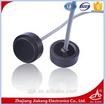
Can any one tell me the application of the following sensr module? Can it be mounted on pipes and then measure the flow rate? Or is it a flow sensor that can just sense the flow when kept directly above flowing water??
The model no of the flow sensors are given below.

TL1000KA
**broken link removed**

TL1000KB http://www.chinaseniorsupplier.com/...r_Flow_Meters_Ultrasonic_Transducer_1MHz.html

Thanks in advance !
 

Re: Application of the following sensor module.

The intended mounting is not clear, at least for the second type I would expect a direct liquid interface.

For a clamp-on flow meter, you need to design an impedance matching block. It might be easier to design it with a bare piezo disk with known properties than with this sensor.
 

Recently I bought a 1Mhz ultrasonic transmitter receiver pair from Alibaba site. The proper datasheet was not available for the same. Since my need for 1 Mhz ultrasonic sensor was urgent, though without proper datasheet I ordered for the same. When it came it had three outlet wires coming out,one in red, one in white and the other one was without any coating,(looks like Aluminium ). Have any one used this sensor module before? If yes can somebody help me with the proper connections that have to be made to each? When I did trial and error,with the uncoated one as ground an red as the input the module is transmitting and at the receiver part also the uncoated one was gnd and the red end was receiving,I was able to receive the signal .But the each white wire of both modules were left open.So is this the proper way of doing it?When I assumed the module as self transmitting and receiving,I checked whether white is receiving any signal,but it didn't. Can somebody help me??
 

Attachments

  • Supply-Efficient-Intelligent-Ultrasonic-Transducer-Mhz-1.jpg
    Supply-Efficient-Intelligent-Ultrasonic-Transducer-Mhz-1.jpg
    92.3 KB · Views: 59
  • IMG-20170407-WA0030.jpg
    IMG-20170407-WA0030.jpg
    502.7 KB · Views: 60
Last edited by a moderator:

The proper datasheet was not available for the same.
There are basic transducer data on the manufacturer web site. They probably thought that the wire connection would be obvious to electronic designers working with this sensor. The company is supplying an amazing portfolio of piezo ceramic devices, but as far as I see they are all pure transducers without electronics. Means receive and transmit function is a job for the external electronics connected to the transducer.

The 1 MHz transducer family seems to be intended for liquid interface, e.g. to be used in doppler flow meters.

I expect the 1200 pF transducer capacitance between white and red wires and a much smaller cable capacitance to cable shield. A multimeter with capacitance measurement feature can clarify. If the connection is obviously different, mail the manufacturer.

By the way, did you ever try to solder aluminium wire? The shield is more likely tinned copper braiding.

- - - Updated - - -

I realized that you started a thread about a similar transducer a month before. Due to the close relation, I merged both threads.
 
  • Like
Reactions: Yadu

    Yadu

    Points: 2
    Helpful Answer Positive Rating
Regarding the same 1Mhz transducer I referred in the previous question....(in the image above..)
I designed a 555 timer at 10khz at the transmitter side and at each rising edge,I got a damped oscillation at the recever transducer,when viewed by using Oscilloscope.Though the resonant frequency of the transducer is 1Mhz, the frequency of the damped oscillation that we obtained was close to 22Mhz. Since we deal with high frequencies right now, is it a right method to directly connnect to oscilloscope and test it? Is it due to the length of the wfre used that the frequency obtained is 22Mhz when the resonant frequency is 1 Mhz? If yes, then how can we test the receving signal?? Is there some alternative?
 

To increase the transmitter energy, you would preferably send a 1 MHz burst, of e.g. 5 or 10 µs duration.

Although the transducer might have additional resonances, you can expect to see a dominant 1 MHz response. What's the test setup? Medium between transmitter and receiver? Distance? How's the receiver terminated?
 

Yes..we tried giving 1Mhz burst using function generator connecting it directly to the transmitter. We checked the output at the receiver by directly connecting oscilloscope to the receiver ends. We got the same damped oscillations. We tried to capture those damped oscillations and measure its frequency.This is when we found it close to 22 Mhz.The voltage given was 8Vpp.

But even though the receiver was disconnected from the oscilloscope the damped oscillations were still present in the oscilloscope.Is this coming because of the length of the wire? We don't understand what the problem is.

After this we designed a bandpass filter from 800khz to 3 Mhz followed by an opamp,TL084.The filter is working properly but the output when given to the opamp,connected as a buffer the output is not as desired. Can you suggest a solution??
 

Also we measured the capacitance across the two wire of the transducer as you told.We got it as 1500pf. What does this capacitance indicate? In order to move forward, what has to be done?
 

1500 pF means you are connecting both piezo transducer terminals, as guessed in post #4.
 

Status
Not open for further replies.

Similar threads

Part and Inventory Search

Welcome to EDABoard.com

Sponsor

Back
Top