Continue to Site

Welcome to EDAboard.com

Welcome to our site! EDAboard.com is an international Electronics Discussion Forum focused on EDA software, circuits, schematics, books, theory, papers, asic, pld, 8051, DSP, Network, RF, Analog Design, PCB, Service Manuals... and a whole lot more! To participate you need to register. Registration is free. Click here to register now.

0-30 VDC Stabilized Power Supply

Status
Not open for further replies.

root2hell

Member level 3
Joined
Aug 13, 2014
Messages
63
Helped
2
Reputation
4
Reaction score
2
Trophy points
8
Location
India
Activity points
394
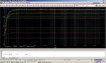
i have made a 30V regulated power supply but i didn't get expected answer.
can anybody help me in that.
i am expecting 30Volts at output.
but getting 20 volts.
i have attached the schematic and TRANS output for 2s.
 

Attachments

  • SCHEMATIC1 _ PAGE1.pdf
    16.6 KB · Views: 128
  • TRANS.pdf
    20.1 KB · Views: 104

hi,
Using a 28V AC voltage source will not be able to give +30Vdc when loaded.
You have two diode voltage drops as well as drops across the series power transistor.
Increase the Vsource to say 37V

I use LTSpice , a 28Vac source would be the Vpeak voltage,, the RMS being only 0.707 of that value.
E
 

R12 on your schematic is supposed to be a trimmer resistor to adjust the maximum output voltage.

The original project at Electronics-Lab used a 24V RMS transformer. It produces about 25.5V without a load then the unloaded positive unregulated supply is (25.5V x 1.414) - 1V= +36V. The output of the voltage amplifier opamp goes as high as about +35V and the driver and output transistors go as high as about 34V so the project can produce +30V when there is no load.

BUT when it has a 4.2A AC load (3ADC from the project) the transformer should produce 24V RMS if it is powerful enough which has a peak of +34V and the bridge rectifier drops it to +32V. Ripple might drop it to +30V. The maximum output of the loaded voltage amplifier opamp might be +28V. The output of the driver and output transistors will be +26V.
The current sensing resistor will have a voltage drop of 1.4V so the maximum output at 3A is only +24.6V, not 30V.

That is why my fixed version uses a 28V or 30V transformer and opamps rated for a supply of 44V max.
28V RMS has a peak of +39.6V. The loaded bridge rectifier drops it to +37.6V. Ripple might drop it to 36.6V if the filter capacitor is larger than the original one. The maximum output voltage of the newer amplifier opamp might be +35V. The output of the loaded driver and output transistors will be +33V. The current sensing resistor will have a voltage drop of 1.4V so the maximum output at 3A is 31.6V so the fixed project can easily provide +30V at 3A.
 

THANKS FOR YOUR VALUABLE REPLY.
my updated circuit is attached but it also gives 21V with no load.
and where i can see the 3A current i cant find it anywhere.
 

Attachments

  • SCHEMATIC1 _ PAGE1.pdf
    24.7 KB · Views: 99

What is the voltage on the Collector of Q3 when, On and Off load.??
E
 

THANKS FOR YOUR VALUABLE REPLY.
my updated circuit is attached but it also gives 21V with no load.
and where i can see the 3A current i cant find it anywhere.
Your new schematic has an input marked 28VAC but it does not say RMS so it might be the peak voltage. Then the maximum output voltage might be only 21V.
This schematic has two values for RV1, 1k and 5k. It has no voltage rating for zener diode U6.
If U6 is a 5.6V zener diode then the output of opamp U1 is +11.2V. If the voltage setting pot R8 is at maximum then the input to opamp U4 is also +11.2V. If RV1 is 5k then opamp U4 has a voltage gain of 2.75 which makes the output +30.8V. If RV1 is 1k then opamp U4 has a voltage gain of 3 and the output will try to be as high as +33.6V but it might be saturated at about +32V.

Your load is 560 ohms so when the output voltage is +30.8V the current in it is only 30.8V/560 ohms= 55mA.
If RV1 is a trimmer resistor and is adjusted so that the output is +30.0V and if there is a load that is 30V/3A= 10 ohms, then the current in the 10 ohms is exactly 3.0A.

- - - Updated - - -

What is the voltage on the Collector of Q3 when, On and Off load.??
Q3 drives the LED. Its collector voltage is almost the same as its emitter voltage when it is turned on and is floating (unmeasurable voltage since there is no current) when it is turned off.
Q3 turns on to warn you that the output voltage is being reduced by the current regulator so that the load current does not exceed the setting of the current setting pot.
 
hi agu,
I am referring to his last posted diagram, which one are you using.??

I am asking the OP to actually measure what he is getting on Q3 collector, the 2N3055 series power transistor,I suspect it will be around 21V.

It should make him aware that his Vin is set too low, as I have already pointed out my post #2.

E
 

Attachments

  • AAesp02.gif
    AAesp02.gif
    49.4 KB · Views: 102
Hi Esp,
He does not know anything about simulating the crippled circuit.
This is the latest version of it:
 

Attachments

  • 0-30V Schematic Rev6 Jul 2014.gif
    0-30V Schematic Rev6 Jul 2014.gif
    23.2 KB · Views: 115

hi agu,
OK, perhaps the OP should use the circuit you have posted an any simulation he runs prior to building it.
Also ensure that he has the sim Vac power source set to the correct RMS value.
E
 

yes i know very less as i am beginner.
but thanks for your replies.
Thanks Audioguru!!!
 

Root 2 Hell,
Do you understand that a transformer voltage is its RMS voltage? RMS voltage is its "average" useful voltage because it swings up and down. 28V RMS provides the same heating power as 28V DC. A SIM program usually uses a PEAK voltage. Maybe your SIM program thinks your PEAK input is only 28V.
The peak voltage of 28V RMS is 28 x (pi/2)= 28 x 1.414= 39.6V. Try using 39.6V as the input voltage.
 
here is the smoke analysis simulation result window....
should i need to change my design before finalize my design
smoke.JPG
 

Root 2 Hell,
Why did you bother making the "smoke test"?
Your copied schematic (your design?) is not correct since it has some wrong values and is missing some parts. The parameters and results in your "smoke test" are very odd.
 

here is my updated circuit and ot works good at Rload>40ohm.
but output get distorted when 10ohm <Rload <20ohm.
this supply is set at output current of 3A.
 

Attachments

  • 30V.pdf
    24.6 KB · Views: 84
  • 30vop.JPG
    30vop.JPG
    219.9 KB · Views: 83

Your simulation shows an awful lot of ripple and very poor voltage regulation. Please describe what you mean when you said it has distorted output.
I notice that your bridge rectifier uses tiny little 1N4148 diodes with a maximum current rating of only 0.2A instead of 10A diodes or a 10A bridge rectifier module that can be bolted to a heatsink.
I also notice that the current setting trimpot R13 is not a trimpot but is a resistor set for a maximum output current of about 2.65A.

The output should have extremely good voltage regulation and such low ripple that it will not show on an oscilloscope.
 

what is the use of R29, R30 and R25.

what should be reduced rating of transformer and rectifier if a want output current of maximum of 1A.
 

What is the use of R29, R30 and R25?
Your schematic of Oct 7, 2014 does not have an R25.
R29 and R30 help to match the base-emitter voltages (Vbe) of the output transistors. Without them, the transistor with the lowest Vbe will pass most of the current which might cause it to over-heat.

What should be reduced rating of transformer and rectifier if a want output current of maximum of 1A?
The transformer passes the peak voltage of 40V and the average current of 1A so it should be rated at 40V x 1A= 40VA which is 40VA/28V RMS= about 28V RMS at 1.41A.
Little 1N400x rectifier diodes will be at their maximum allowed temperature if they are cooled well but they will probably over-heat and fail if they are inside an enclosure. Use a 5A rectifier bridge module bolted to the metal chassis.
 

should i lower RSENSE to about 0.27ohm for 30V 1A power supply.
coz i am getting ripples at setting current POT to minimum current.

- - - Updated - - -

i have replaced that diode with R25 1k resistor.
 

As Audioguru stated you must start with diodes rated 10A or more due to internal resistance. When the transformer charges up the capacitor on the rising peak with 10mF or more it is only turned on for a short time. <25% max after power up.

Then the peak current must be 4 to 5x your transformer rated current because of the % duty cycle for ripple voltage and current.


The diodes are off 75 to 80% of the time while the big cap supplies the current and then it must work 4 to 5 times harder to maintain 3Aout , thus 12 to 15A is ideal for diode ratings, but 10A may be adequate for you.

Also for low voltage drop, these should be low voltage Schottky power diodes that will cut your voltage drop on the bridge and reduce high temps. @ 3A without heatsinks, otherwise ,more VI=P drop, more heat , now need a heatsink with 4 diodes or a bridge diode in 1 part.

These can get more expensive, but that is the problem with linear 50Hz to DC regulated power supplies. cost per Watt and efficiency.


this also explains your temperatures of D1-4 (not accurate but ) in the Smoke Test, they would have smoked.

normally a good design does not exceed 85C hot spot at max ambient temp... Not the 200deg C spec in hotspot or the simulation withan unlimited power transformer and diodes at 1.xxxk deg C thats over 1000 deg C
:grin:

because the voltage source (XFMR) winding resistance was excluded in your SImulation.

Now you know.
 
Status
Not open for further replies.

Similar threads

Part and Inventory Search

Welcome to EDABoard.com

Sponsor

Back
Top