Continue to Site

Welcome to EDAboard.com

Welcome to our site! EDAboard.com is an international Electronics Discussion Forum focused on EDA software, circuits, schematics, books, theory, papers, asic, pld, 8051, DSP, Network, RF, Analog Design, PCB, Service Manuals... and a whole lot more! To participate you need to register. Registration is free. Click here to register now.

Power supply

Rajinder1268

Full Member level 3
Joined
Mar 20, 2021
Messages
162
Helped
1
Reputation
2
Reaction score
4
Trophy points
18
Activity points
1,228
Hi all,
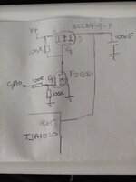
I have attached a circuit and need some feedback. I need to disconnect and reconnect the Vsupply (12V filtered from.car battery) to a LIN transceiver (tja1020) I have used a n channel device to pull the gate of the p channel fet under the control of a microcontroller GPIO.
The p channel device is BSS84-7-F and the n channel fet is FDV303N. The n channel is a logic level fet. I wanted to ask if there is anything that looks incorrect on my circuit and if so what the remedy would be. Also if there is an easier way of disconnecting the supply.
 

Attachments

  • IMG_20230607_074211.jpg
    IMG_20230607_074211.jpg
    1.7 MB · Views: 68
Looks like it should work. Those 100K resistors seem awfully high, though. Why don’t you simulate it?
I have used the 100K pull down before for the n channel fet. I wasn't sure about the value for the 100K to keep the pfet off. Is there a good way to calculate this?
 
It depends on the layout as stray capacitance , inductance and CISS , Miller Capaitance asnd load inductance affect Flyback voltage (negative). The Load cap and any motor stored energy needs to be added to the simulation. but so far, it looks ok. For motor loads a negative spike snubber might be necessary or Vds clamp not a diode to ground which might not handle it.,
 
Hi,
I have used the 100K pull down before for the n channel fet. I wasn't sure about the value for the 100K to keep the pfet off. Is there a good way to calculate this?
For sure: Ohm' s Law.
I: maximum expectable stray current of the whole node.
V: maximum allowed V_GS to keep FET OFF.

For my taste 100k isn't too high. I even used 1M on (coin) battery operated designs to keep current low.

Klaus
 
What is "12 V filtered from car battery"? Does filtering include effective overvoltage protection? Input overvoltage >20V will kill the PFET.
 
What is "12 V filtered from car battery"? Does filtering include effective overvoltage protection? Input overvoltage >20V will kill the PFET.
Hi, yes you are correct. The 12V from the car battery has a pptc fuse, then reverse polarity protection diode, TVS diode and then filtered through a EMI filter BNX002-11.
 
Which TVS diode? Guess clamp voltage can easily exceed 20 V. You should at least consider gate voltage clamp for P-FET (series resistor + zener).
 
Which TVS diode? Guess clamp voltage can easily exceed 20 V. You should at least consider gate voltage clamp for P-FET (series resistor + zener).
The TVS diode is SMC3K24CAHM3/57
--- Updated ---

The TVS diode is SMC3K24CAHM3/57
What value of zener for the gate voltage? The vgs of the pfet is 20V,would a 10V zener 1N4740A and 10K resistor be sufficient?
 

LaTeX Commands Quick-Menu:

Similar threads

Part and Inventory Search

Welcome to EDABoard.com

Sponsor

Back
Top