Continue to Site

Welcome to EDAboard.com

Welcome to our site! EDAboard.com is an international Electronics Discussion Forum focused on EDA software, circuits, schematics, books, theory, papers, asic, pld, 8051, DSP, Network, RF, Analog Design, PCB, Service Manuals... and a whole lot more! To participate you need to register. Registration is free. Click here to register now.

planar inductor or capacitor

Status
Not open for further replies.

rathankh

Newbie level 5
Joined
Aug 4, 2016
Messages
8
Helped
0
Reputation
0
Reaction score
0
Trophy points
1
Activity points
70
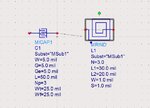
Dear sir does the same equations will be valid if the inductor or capacitor are in shunt...
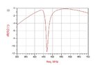
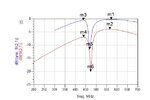

Y11 = Im(Y(1,1))

C1=1.0E12 / ( 2 * _PI * _FREQ * ( 1 / Y11 ) )

Where
L1=1.0E9 * ( 1 / Y11 ) / ( 2 * _PI * _FREQ )

L1: Effective Inductance (in nH) of a series RL network

C1: Effective Capacitance (in pF) of a series RC network

_FREQ: is project frequencies in GHz


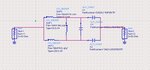
Please let me know what are the changes to be done to model the same in to capacitor or inductor 's planar equivalent.

Thnaks
 

Y11 = Im(Y(1,1))
C1=1.0E12 / ( 2 * _PI * _FREQ * ( 1 / Y11 ) )
L1=1.0E9 * ( 1 / Y11 ) / ( 2 * _PI * _FREQ )
Where
L1: Effective Inductance (in nH) of a series RL network
C1: Effective Capacitance (in pF) of a series RC network
_FREQ: is project frequencies in GHz
Completely Wrong.

2-Port Y-Parameters can not exist for shunt DUT.
So I assume following.

(1) You do 1-Port measurement of shunt DUT.
Z(1,1) = 1/Y(1,1)

(2) Modeling DUT as RL-Series or RC-Series equivalent circuit.

Code:
C1 = -( 1/imag( 1/Y(1,1) ) ) / (2*pi*_FREQ*1e9) / 1e-12
     = -1e3 * ( 1/imag( 1/Y(1,1) ) ) / (2*pi*_FREQ)

L1 = imag( 1/Y(1,1) ) / (2*pi*_FREQ*1e9) / 1e-9
    = imag( 1/Y(1,1) ) / (2*pi*_FREQ)
 
Last edited:

Completely Wrong.

2-Port Y-Parameters can not exist for shunt DUT.
So I assume following.

(1) You do 1-Port measurement of shunt DUT.
Z(1,1) = 1/Y(1,1)

(2) Modeling DUT as RL-Series or RC-Series equivalent circuit.

Code:
C1 = -( 1/imag( 1/Y(1,1) ) ) / (2*pi*_FREQ*1e9) / 1e-12
     = -1e3 * ( 1/imag( 1/Y(1,1) ) ) / (2*pi*_FREQ)

L1 = imag( 1/Y(1,1) ) / (2*pi*_FREQ*1e9) / 1e-9
    = imag( 1/Y(1,1) ) / (2*pi*_FREQ)

Dear sir i am tying to model below circuit(tank) into its distributed(DC) equivalent circuit.I am able to model the series L/C but the shunt L/C 82nH and 1.2pF respectively are causing very large fluctuations in results when they are modeled to their distributed equivalent.I have applied same formula to calculate their inductance and capacitance as i mentioned in my first query.So my question is that can we model shunt L/C into distributed equivalent with respect to my circuit??If yes how?....if no why it can't be?
Can those same formulas be use to calculate shunt L?C.
Please help.

Thanks
 

Attachments

  • DC.jpg
    DC.jpg
    57.6 KB · Views: 66
  • tank.jpg
    tank.jpg
    83.3 KB · Views: 68

Look at this Application Note of Volker Muhlhaus because you do something wrong.
https://muehlhaus.com/support/ads-application-notes/inductor-em-ports


Dear sir i am tying to model below circuit(tank) into its distributed(DC) equivalent circuit and obtained the results in (fig1).I have modeled its distributed equivalent as in (figure2) and i have g0t results as in (figure3) which are almost satisfactory.But as i the shunt L/C 82nH and 1.2pF respectively(figure4) are causing very large fluctuations in results (figure5)when they are modeled to their shunt distributed equivalent.I have applied same formula to calculate their inductance and capacitance as i mentioned in my first query.So my question is that can we model shunt L/C into distributed equivalent with respect to my circuit??If yes how?....if no why it can't be?
Can those same formulas be use to calculate shunt L?C.
I am stuck in this.Please help.

Thanks
 

Attachments

  • DC.jpg
    DC.jpg
    57.6 KB · Views: 62
  • tank.jpg
    tank.jpg
    83.3 KB · Views: 53
  • fig1.jpg
    fig1.jpg
    27.2 KB · Views: 66
  • figure2.jpg
    figure2.jpg
    132.1 KB · Views: 54
  • figure3.jpg
    figure3.jpg
    44.6 KB · Views: 62
  • figure4.jpg
    figure4.jpg
    124.6 KB · Views: 56
  • figure5.jpg
    figure5.jpg
    42.8 KB · Views: 60

Dear sir i am tying to model below circuit(tank) into its distributed(DC) equivalent circuit and obtained the results in (fig1).I have modeled its distributed equivalent as in (figure2) and i have g0t results as in (figure3) which are almost satisfactory.But as i the shunt L/C 82nH and 1.2pF respectively(figure4) are causing very large fluctuations in results (figure5)when they are modeled to their shunt distributed equivalent.I have applied same formula to calculate their inductance and capacitance as i mentioned in my first query.So my question is that can we model shunt L/C into distributed equivalent with respect to my circuit??If yes how?....if no why it can't be?
Can those same formulas be use to calculate shunt L?C.
I am stuck in this.Please help.

Thanks
I have looked at you set-up and inductor physical dimensions are not meaningful because your frequency is too low for these kind of planar inductors.How do you calculate the inductor values ? I guess the PDK that you have been using computes automatically the rough inductor values right ?? If it's so, the validity must have a range.9mil is too thin for a 500 MHz inductor and few hundred nH inductor values are not practical for planar inductors which are on a substrate.
 
I have looked at you set-up and inductor physical dimensions are not meaningful because your frequency is too low for these kind of planar inductors.How do you calculate the inductor values ? I guess the PDK that you have been using computes automatically the rough inductor values right ?? If it's so, the validity must have a range.9mil is too thin for a 500 MHz inductor and few hundred nH inductor values are not practical for planar inductors which are on a substrate.

Sir,First thank you very much for your reply.I have tried trail and error method to obtain required values of L/C.But sir,if it is working for series components why cant it work for shunt one.
Sir,why 9mil at 500 MHz inductor for few hundred nH inductor values are not practical for planar inductors.
Sir,Please let me know where i am doing wrong. Please suggest me any alternatives.

Thanks,
 

Can those same formulas be use to calculate shunt L?C.

No. These simple equations are for parallel RC or series RL only. They are not useful for LC combinations.

For your case, I would design L and C separately.
The distributed L has some parasitic capacitance. First design that L and calculate that parasitic capacitance from self resonance, so that you can know the required parallel C.

Good luck!
 
Last edited:
No. These simple equations are for parallel RC or series RL only. They are not useful for LC combinations.

For your case, I would design L and C separately.
The distributed L has some parasitic capacitance. First design that L and calculate that parasitic capacitance from self resonance, so that you can know the required parallel C.

Good luck!

Dear sir,Thanks for the reply.
Can you please let me know how parasitic capacitance of distributed L is calculated.What formula's should be used.Can you let me know how it is done with an example.It will be very helpful. Please consider my request.

Thanks
 

Dear sir,

I the distributed model of inductors the values of L and R(1/Y(1,1) are approximatley same when compared to lumped inductors but for Q factor their is significantly large difference.Considering 36nH lumped inductor it has Q=58 while its diatributed equivalent has Q=2.54E4,their is lot of difference.
Same is the case with C,capacitance and R values are approximately samebut its dissipiation factor is of large value.
Can you let me know why is this may be?...please help me

Thanks in advance.
 

Status
Not open for further replies.

Part and Inventory Search

Welcome to EDABoard.com

Sponsor

Back
Top