Continue to Site

Welcome to EDAboard.com

Welcome to our site! EDAboard.com is an international Electronics Discussion Forum focused on EDA software, circuits, schematics, books, theory, papers, asic, pld, 8051, DSP, Network, RF, Analog Design, PCB, Service Manuals... and a whole lot more! To participate you need to register. Registration is free. Click here to register now.

modification for power supply

Status
Not open for further replies.

Newwbie

Newbie level 6
Joined
Feb 18, 2017
Messages
14
Helped
0
Reputation
0
Reaction score
0
Trophy points
1
Activity points
124
Sorry to tell but i have very limited knowledge and was recently introduced to the fields of electronics.
So, ive bought this Elenco AC/DC Triple Output Power Supply Kit and plan to build it myself as an experiment/experience. However this is my first ever project i have bought online and i am determined to dedicated my time and work to create this project with my hands. Link:https://www.amazon.com/Elenco-Tripl...73997&sr=8-1&keywords=elenco+power+supply+kit

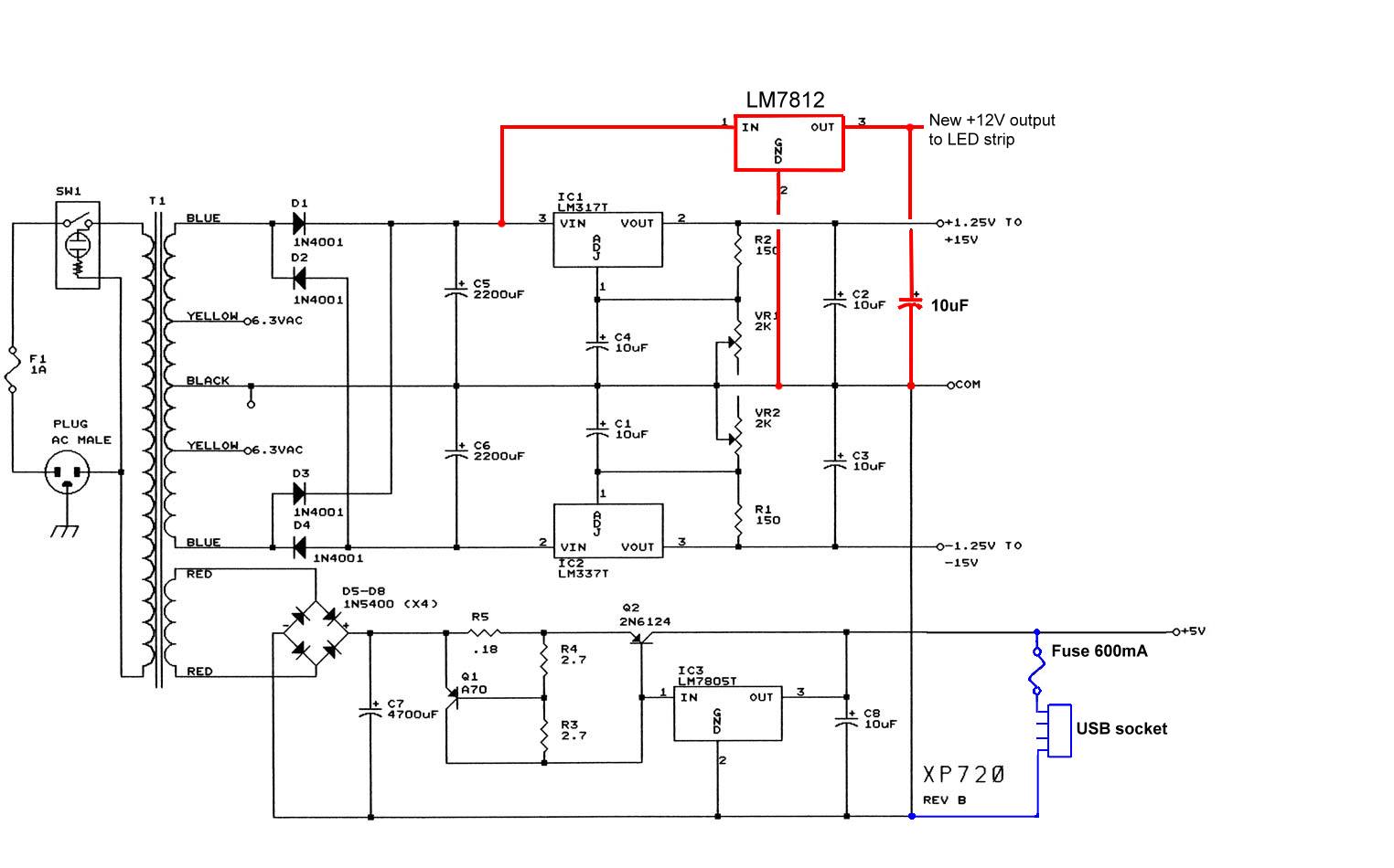
With that being said i am curious to add special modifications onto this power supply kit and i am very eager to add some led strips with this project (of course i must also change the design to see the effect). I thought maybe an led strip would be awesome to put inside this power supply - **broken link removed** Also i would like to add an additional USB port to charge my devices. Once again thank you so much, any tips or recommendations you would like to share, would be much appreciated as this is my first ever project ill be making myself, so therefore, im going to need all the help i can get. Thank you :grin:
 

I wouldn't bother with the LEDS, the strip is longer than the powers upply is wide! Also, there is no specification for the current drawn by the LEDs but it wouldn't be out of order to think they would consume half the total output power of the PSU so you would only have what's left to use for other purposes.

You can simply add a suitable USB connector and wire it's +/- power pins to the PSU output as long as you set the voltage to 5V. Ideally you would incorporate a fuse to protect from overload. If you want to ensure the USB 5V is present at all times, regardless of the controls settings, you would have to show us the schematic of the supply so we can see how it can be modified.

Brian.
 
Wow thank you so much for replying!
By installing the led strips i was thinking about this kind **broken link removed** because im thinking of changing the design of course or else the leds wouldnt be visable!.Ive also got some voltage regulators and a buck converter, so is a fuse still compulsory.
Here is a picture of the schematic diagram.
schematic elenco.jpg
Thank you so much for the reply, thought no one would understand because i am really new to this subject of electronics.
 

Your choice but I would seriously suggest you didn't use a LED strip unless you want lighting effects. It will take away quite a sizeable amount of power you could use for other things and also restrict the range of voltages you can sensibly set the power supply to produce. You can't shorten those strips so you can't mount them on the PSU itself.

For your USB output you can connect directly to the output of the 5V regulator (across C8) but please add a fuse, it can supply more current than a standard USB connector can carry so you risk a melt down if a fault occurs. Normal USB outlets have a maximum rating of 0.5Amps but the current limiting circuit in the power supply doesn't cut in until about 3 Amps are flowing. Also be aware that although USB connectors normally carry 5V, there is also a standard for signalling to the charger to cut the feed when the battery is full. It uses the USB signal wires and is quite complicated to implement, most chargers have dedicated controller ICs in them and they are difficult to buy in small quantities to use in a DIY project. They also tend to be incredibly tiny (3 x 3 x 0.5mm) and need special soldering equipment to mount them!

Brian.
 

Sorry but the LED strips is a must for my project!!. I will figure out a way to fit these LED strips inside the case. I just need help on the installments, on where the positive and negative goes and make sure it does not explode on me. I also forgot to mention that i will be implementing a voltmeter inside this project which also includes a current shunt DC, so what should i connect it with, my step down buck converter? (the LEDs, USB connectors and the voltmeter is a must for this project!!!)

So i connect the C8 wire with my 5V regulator and link it with the LED strips, usb ports and perhaps my voltmeter?.Could you link me to the specific fuse needed to prevent the USB connector from risking an overload. Also i think these USB connectors already have controller ICs components on this circuit. **broken link removed**
 
Last edited by a moderator:

Hi,

When you say "C8 wire" I understand the +5V out terminal/wire. As Brian has already said - the +5V output will use a lot of the current budget just for the LED strip, (unless the LEDs only need a couple of mA each).

The voltmeter should go between the +5V out and COM, or maybe far more useful - between the +1.25 to 15V and COM, and a second voltmeter/or the -1.25V to -15V and COM, unless the aim is to be sure the USB 5V is 5V.

If you're adding a second 5V regulator, then you would want to connect it from the point at C7, where the bridge and filter section ends. Or C5, depending on which part can spare the current you expect will be needed.

Look for a fast blow fuse that is just over the USB current, i.e. 600mA, but I'd just get a 500mA fast fuse. Littelfuse, amongst others, have helpful resources for fuse selection guides. Fuse Selection Guide and Fuseology Selection Guide are good (1 and 3 in the results list).
 
Last edited:

This is starting to get confusing.

That PSU has:
1. a 6.3V-0-6.3V AC output.
2. a 5V DC fixed output
3. an adjustable +1.25V to +15V DC ouput
4. an adjustable -1.25V to -15V DC output.

Note that they all share a common ground point, you cant use them in isolation of each other.

So which output do you want to feed the USB charger socket?
Which output(s) to you want to measure with your voltmeter?

Yes the link to the Ebay USB board has the necessary protection components on it already but it takes 12V as it's input so you would have to tie up one of the adjustable outputs and leave it set to 12V to feed that board. I would make more sense to use the existing 5V output and add a fuse, that doesn't give you the programmable USB current limit of the Ebay board but it is far simpler to build and it leaves the other supplies free for other purposes. The fuse should be rated a little higher than the 500mA maximum allowed for a USB socket so one rated at 600mA would be suitable. Don't forget it may need changing if it blows so mount it in a front panel fuse holder.

Brian.
 

So pretty much i should attach the USB connector and the LED strip to the +5V output along with a fuse soldered onto the USB to prevent a current overload. The voltmeter will be attached to the +1.25 to 15v. So is a second regulator a must for this circuit. Also sorry if this has been said already but, where which output do i attach the step down converter and which component will be using it. Thank you all so much for replying, you all have given the inspiration and confidence to build this project. I hope i haven't confused anyone, i am still new to this subject.
 

You don't need a step down converter.

The LED strip works from 12V so you tie up one of the adjustable outputs to drive it and have to leave it set to 12V. The LEDs won't light up with much less than 12V and that strip has no regulator of it's own so if you put more than 12V in to it the chances are the LEDs will burn out. You might be able to add an extra FIXED 12V regulator to the circuit just to drive the LEDS but bear in mind you can't just keep adding more loads to the transformer, it has to manage the total of all the loads so the new fixed 12V regulator and the LEDs will reduce the available power to the other outputs.

If you do add a fixed 12V regulator, use a type 7812 with it's 'IN' pin connected to the + side of C5, it's 'GND' pin connected to the - side of C5 (with short wires!) and take the 12V output for the LEDs from the 'OUT' pin. Also add a capacitor of about 10uF from the 'OUT' pin to the 'GND' pin. Note that it will need to be fitted with a heat sink like the other regulators but DO NOT share the same heat sinks!!! The metal tab on the regulators have a voltage on them and you must never let the mounting screws allow them to make connection to each other.

The voltmeter connection really depends on the type of meter you want to add. If it is a mechanical meter with a moving needle against a scale, you just connect it across the voltage you want to measure with a suitable series resistor. If you want to use a digital one with an LED or LCD display, things get a bit more complicated because the circuit that does the measuring and the display itself generally need a regulated supply of their own. How they are wired depends very much on the design of the voltmeter module, for example you might use one that measures 0 to 15V but needs a fixed 5V to power it's own circuits. Whether or not you can use one of the voltages already present to power it depends on the type of module, some require an isolated supply which makes the circuit far more complicated.

Brian.
 

sweet, so the LED strip will work regardless of needing to add a 12V regulator. Also the USB connectors must be attached to the +1.25 - 15V with the use of a 600mA fuse. So those two are taken care off.
Now for the voltage meter, ive bought an LED digital voltage meter which provides both the voltage and amp usage, it also includes a current shunt which is needed to power the voltage meter. Do i also connect it to the +1.25 - 15V output?. **broken link removed**
Again thank you so much, this project is really going as planned.
 

Sorry but in this case, how would i connect the fuse with the USB connector?.
 

I have this exact same power supply which I bought many years ago.

I added 4 modifications to improve its usefulness:

-1) Replaced both potentiometers with 10-turn ones. This is by far the easiest and the best modification. It makes very easy to adjust the voltage very precisely.

-2) Added a dual voltmeter to monitor the outputs. It is a pain to reach for your multimeter any time you want to adjust the voltages.

-3) Added a multipole relay which will turn on or turn off all voltages simultaneously. This is very important, improper voltage sequencing can latch up the circuit being powered.

-4) Added a temp sensor and a small fan to the heatsink.

I would suggest that you do something similar first. Then you can add cosmetic details like the LED strip.
 

sweet, so the LED strip will work regardless of needing to add a 12V regulator
Yes, but only if you connect it to one of the variable outputs and set the voltage to 12V! Less voltage = no lights, more voltage = smoke.
Also the USB connectors must be attached to the +1.25 - 15V with the use of a 600mA fuse. So those two are taken care off.
The USB connector must ONLY be wired to 5V. Connect the '-' pin of the USB connector to ground and the '+' pin to the fuse holder. The other side of the fuse holder goes to the fixed 5V output

The meter module should work but note it needs a fixed supply of 4.5V to 30V to power it's own internal circuitry and display. I would suggest you wire those pins (the red and black ones in the diagram) to the power supply fixed 5V output. IMPORTANT - it can only be used to monitor the positive output!!! If you wire it to the negative output it will be damaged. You need even more circuits if you want to monitor the negative supply as well.

Brian.
 

Yes, but only if you connect it to one of the variable outputs and set the voltage to 12V! Less voltage = no lights, more voltage = smoke.
The USB connector must ONLY be wired to 5V. Connect the '-' pin of the USB connector to ground and the '+' pin to the fuse holder. The other side of the fuse holder goes to the fixed 5V output

Is this the right fuse and fuse holder?.**broken link removed** . The only 600mA fuse ive found is a fast-blow fuse, which i have no idea how to link it with the usb connectors.

Now for the volt meter, do i connect it to the same 5v output as the USB connectors is that what you are trying to say? Or just the +1.25-15V but just cahnge it to a fixed 5V output. Also what about the blue,yellow and green wires, where do i connect those to?.Also what do i do with the shunt.
 

Now for the volt meter, do i connect it to the same 5v output as the USB connectors is that what you are trying to say? Or just the +1.25-15V but just cahnge it to a fixed 5V output. Also what about the blue,yellow and green wires, where do i connect those to?.Also what do i do with the shunt.

The no-name voltmeter and ammeter should come with a wiring diagram, I haven't been able to find one just now and it makes no sense to assume other similar devices will be the same. When you get it, if you can't figure it out, then scan it and post an image.

It looks like the ammeter has 2 sensing wires, and the shunt must be placed in series with the load whose current you wish to measure, before the load, not after, and two of the wires will also be connected to the shunt. If it runs off 5V, I'd be surprised if it used a lot of current to say the least, and the 5V output presumably can carry the USB output and a tiny amount to power the meters, but the display LEDs may use a fair amount of current... Until you get the spec sheet and wiring diagram it is impossible to guess with certainty.

Maybe another user knows this meter and can advise you.
 

There is a wiring diagram and brief (too brief!) specification on the web site but I thought it best to treat this project in stages.

Basically, there is fixed supply to run the meter electronics and three measuring connections, ground, a feed from before the shunt and a feed after it. The voltage is measured at the output side of the shunt (I assume) and the current is measured by taking the difference from before and after the shunt. As you say, the unit should come with it's own wiring diagram and it may be different to the one on the web site, best to see the one supplied with it before advising on how to connect it.

Brian.
 

Sorry i got one more really noobie question here.

Do you know where in this circuit board is the 5V output and 1.25+ - 15V located in?. I understand the schematic but im bad at translating it with a PCB board. Sorry i know, its a really dumb question :/
Elenco circuit board.jpg
 

Status
Not open for further replies.

Part and Inventory Search

Welcome to EDABoard.com

Sponsor

Back
Top