Continue to Site

Welcome to EDAboard.com

Welcome to our site! EDAboard.com is an international Electronics Discussion Forum focused on EDA software, circuits, schematics, books, theory, papers, asic, pld, 8051, DSP, Network, RF, Analog Design, PCB, Service Manuals... and a whole lot more! To participate you need to register. Registration is free. Click here to register now.

Arduino died after connecting to Laptop(A4988)

Status
Not open for further replies.

xmen_xwk

Full Member level 3
Joined
Sep 12, 2014
Messages
172
Helped
2
Reputation
4
Reaction score
2
Trophy points
18
Activity points
1,373
I have 2 A4988 drivers connected to arduino, also their VDDs and GNDs are connected to arduino. Everything was working quite fine if I was powering the arduino with 5V from laptop's USB. But now I thought to power the arduino with separate PSU of 11V along with 24v motor psu.

I connected the 11V PSU to RAW and GND of arduino
Removed all connections of laptop
When I powered both Power supplies(with same AC cable), arduino turned on.

but as I connected the entire board to laptop USB jack(Not the VCC, only GND, RX, TX and DTR), arduino turned off quickly and didn't came back on.


Why did this happen ? How should I fix this so it doesn't happen to next arduino.


Also here is the picture showing how all is connected, but only showing one driver.
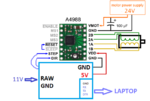
a4988 diagram.png

PS : Laptop was on battery.
 

Hi,

You used a switch mode power supply? They are worse than usual 50Hz transformer supplies.

In general:
You need to protect ANY IO line that enters/leaves the board against overvoltage.

Or you need connectors with leading GND pins, to ensore that GND is the first signal to be connected.

Klaus
 

Hi,

There are dedicated protection devices available.
Some are calle d "USB" protection diodes, but you may use them for other IO, too.

One is IP4220CZ6.

I recommend to add two resistors (maybe 100R each) before and after the protection diodes ...in sereies with the data lines

Klaus
 

Hi,

There are dedicated protection devices available.
Some are calle d "USB" protection diodes, but you may use them for other IO, too.

One is IP4220CZ6.

I recommend to add two resistors (maybe 100R each) before and after the protection diodes ...in sereies with the data lines

Klaus

But on which pins should I do that ? did TX line destroy it ?
 

Hi,

But on which pins should I do that ? did TX line destroy it ?
How can I know which one of the pins destroyed the IC? I only have the informations you gave in this thread.


You need to protect ANY IO line that enters/leaves the board against overvoltage.

To focus it: You need to protect ALL IO lines that enter/leave the board/case against ESD.

Klaus
 

Status
Not open for further replies.

Part and Inventory Search

Welcome to EDABoard.com

Sponsor

Back
Top