Continue to Site

Welcome to EDAboard.com

Welcome to our site! EDAboard.com is an international Electronics Discussion Forum focused on EDA software, circuits, schematics, books, theory, papers, asic, pld, 8051, DSP, Network, RF, Analog Design, PCB, Service Manuals... and a whole lot more! To participate you need to register. Registration is free. Click here to register now.

testing out issues on a preamp

Status
Not open for further replies.

Enzy

Advanced Member level 1
Joined
Mar 20, 2016
Messages
488
Helped
2
Reputation
4
Reaction score
2
Trophy points
18
Activity points
4,607
I build the basic amplifier circuit of a tda7293 it plays well but I wanted more volume so I decided to try a simple preamp circuit but it seems there is a high pass filter of some sort and also the circuit doesnt play clean.

I need all the frequency ranges from the amp just the same now I am not getting any bass only high mid.


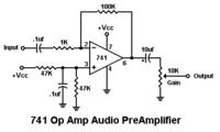
could anyone assist me with fixing these issues.
 

Hi,

In my eyes this is an example of a bad designed circuit.
* 0.1u and 1k input LPF creates a high pass filter with 1600Hz cutoff frequency
* 1k and 100k generates a gain of 100, but the 741 is not suitable for this (high frequency cutoff)
* an electrolytic capacitor in an audio path generates distortions
* 741 is not suitable at all for audio circuits (if you expect some quality)...expect noise and distortions

--> look for another preamp circuit ...with audio quality. There are plenty good circuits in the internet.

Klaus
 
  • Like
Reactions: Enzy

    Enzy

    Points: 2
    Helpful Answer Positive Rating
ok then thanks. I have a tl072 ill try next.

- - - Updated - - -

How does this circuit look? and if this is a good enough circuit can I ignore r11 ( meaning to leave it out of the circuit)
.

- - - Updated - - -


Hi,

Better.

Ignore R11.

If you want even higher sound quality then simply replace the electrolytic capacitors with foil capacitors.

Klaus
 

ok will do. I dont have a 100pf capacitor and I cant get one to buy which value can I use to replace that?

also the 1uf and 2 uf capacitors I only have some electrolytic caps to use in those places I cant get those values with other types of caps.
 

Hi,

the values are not that critical. (In this circuit: Maybe you hear the difference between 100pF and 1000pF, but you wont hear the difference of 100pF to 120pF)

The electrolytics are O.K.... maybe later you can test other capacitors.

Don´t use ceramic capacitors like Z5U or Y5V.
--> Use X7R or better for high capacitance and COG/NP0 (even better) for low capacitance .

Klaus
 

Simple arithmetic shows that the 1uF input capacitor feeding the 100k R4 produces a cutoff frequency at an earthquake frequency of only 1.6Hz which is silly. I would use a 220nF (0.22uF) film capacitor for a cutoff at 7.3Hz then audio will be flat down to 20Hz.

I would use a 1uF film capacitor for the 2uF one.
 

Ok then I built it and tested it, it works ok but i here some noise coming from the speakers not too loud though how can I fix that
 

Hi,

We can' t hear the sound, so either describe it or show a scope picture...or even better an FFT plot.

Do you have a solid GND plane? You will need it.

Klaus
 

Ok then I built it and tested it, it works ok but i here some noise coming from the speakers not too loud though how can I fix that
A low frequency hum sound has a fix (use a shielded audio input cable) that is completely different than if the sound is a high frequency hiss (use an opamp with less noise like an OPA134).
 
  • Like
Reactions: Enzy

    Enzy

    Points: 2
    Helpful Answer Positive Rating
Status
Not open for further replies.

Part and Inventory Search

Welcome to EDABoard.com

Sponsor

Back
Top