Continue to Site

Welcome to EDAboard.com

Welcome to our site! EDAboard.com is an international Electronics Discussion Forum focused on EDA software, circuits, schematics, books, theory, papers, asic, pld, 8051, DSP, Network, RF, Analog Design, PCB, Service Manuals... and a whole lot more! To participate you need to register. Registration is free. Click here to register now.

[SOLVED] Oscilloscope Philips PM3302

Status
Not open for further replies.

newtonsrl

Junior Member level 3
Joined
Jan 28, 2016
Messages
29
Helped
0
Reputation
0
Reaction score
0
Trophy points
1
Activity points
222
Hi,
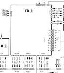
today my oscilloscope is dead. The problem started a few days ago, but giving some tap the houses continued to function until it stopped working. I disassembled everything, cleaned with compressed air and reassembled. But it does not work. If I try to connect the two power diodes D1103 and D1104 will burn. I replaced the original EM513 with 1n4007. I have disassembled again eveything, and on anothe board I found a BD237 burnt. May be this last was the real problem, but at the moment I cannot understand why my two diodes will burn when I give power supply. Someone could give me some guidance on how to try to solve the problem? I am very sad :-( because I was very attached to my oscilloscope and I would be very grateful if someone could help.
In attachment the schematics of the board.
Thanks.
 

Attachments

  • Hameg_HM208_page40.pdf
    103 KB · Views: 142

giving some tap the houses continued to function

This suggests there's a physical contact making and breaking. A wire wiggling could be obvious if it's in the open. Maybe it's something inside the CRT? A bad ground is a common source of trouble in any installation. Can you find a loose screw, with a wire attached? Maybe it just needs tightening.

Try picking the scope up. Turn it at different angles. This might make the contact connect again. You will need to look inside, in an effort to spot what's going on.
 

Already checked, but not success... the problem now is the two diodes. Why it burns? Where can be the short circuit?
Thanks for your help at all.
 

D 1103-1104 feed the -5V 0.3A supply. Since they burn, it could be because the 7905 has shorted. Or maybe one of the smoothing capacitors. Each capacitor should be disconnected, and ohm-checked out of circuit.

You should check the circuitry which runs from the -5V. It's labelled for 0.3A. Can you attach an external 5V supply (inverted to get -5V)? Can you monitor current draw?

There a question whether overmuch current draw would burn the diodes but not the 7905 IC. It would help if you could determine what part gets overheated, but the scope doesn't work at this point.

It might help if you put a low-ohm resistor in the line, at strategic locations, to limit current through that part of the circuit. It might save the diodes during testing of the scope. Try 3 ohm, then 2, then 1. If you're lucky the voltage drop will not be too much.
 
Either IC1101 is faulty or you have a short on the -5V line feeding into the rest of the scope. Furthermore, make sure that C1102, C1105, C1109 or C1110 is not low resistance. If you can unplug or disconnect the power-supply lines from the rest of the scope, you can test to make sure all your regulators function normally.
 
Is there a way to unplug all of the boards using the power supply and see if the diodes burn out with only the power supply powered up, and then reconnect one board at a time to find the problem board.
 

I've apparently solved the power supply problem. Now the oscilloscope stay on. I've found the last one BD237 in a shop in Brussels. Now the crt is on, but i see only a point, see picture. Rotating the base time selector I see the point moving, but no correct signal showing. Touching the calibration signal reference on the front panel of the scope nothing happen.
The time base selector is composed by three rotating multi switch. When I have remounted the board, may be I've lost the synchro between the three wheels... May be this the problem?
Otherwise what could be? Thanks for any advice. DSC_0011.JPG
 

You will have to upload the complete circuit diagram if you want us to try to help you with this.
 

hameg hm 208 manual - PHILIPS PM3302
Hameg_HM208-28.jpgHameg_HM208-29.jpgHameg_HM208-30.jpgHameg_HM208-31.jpgHameg_HM208-32.jpgHameg_HM208-33.jpgHameg_HM208-34.jpgHameg_HM208-35.jpgHameg_HM208-36.jpgHameg_HM208-37.jpgHameg_HM208-38.jpgHameg_HM208-39.jpgHameg_HM208-40.jpgHameg_HM208-41.jpgHameg_HM208-42.jpgHameg_HM208-43.jpgHameg_HM208-44.jpgHameg_HM208-45.jpgHameg_HM208-46.jpgHameg_HM208-47.jpgHameg_HM208-48.jpgHameg_HM208-49.jpgHameg_HM208-50.jpgHameg_HM208-51.jpgHameg_HM208-52.jpg
 

Can you upload it as a PDF bundle? It will make it much easier to flip between pages.

If you put the scope in X-Y mode can you move the dot with the X and Y controls, and with an external voltage applied to X and Y inputs?
 

I had a problem with IC1101 7905 and the diode D1103 and D1104, TB (Time base?) board, page 40 of the manual. the board image is on page 38.
I replaced two times the diodes. I replaced the originale 7905 with LM7905. The original is an "isolated version", with case connected to chassis. The LM7905 has the vout on the case... So the first time I gave power supply obviously evrything burnt.
I'm following the trace of -5V, that with a 26 pole connector go to ZW board, as shown at page 28. From this schematics seems that -5V works only on this board. If the problem was been caused by my fault, the problem should be found here.
thanks to everybody for the help.

- - - Updated - - -

hameg hm 208 manual - PHILIPS PM3302View attachment Hameg_HM208.pdf

- - - Updated - - -

I cannot move the dot in any way. And it is not a dot... it is a short line that changes if I move the base time selector.
 

Are ALL the voltages present and normal on the power supply?
 

Yes, now all the voltages shown on the schematic pag 40 (+5V -5V +12V) are ok.
 
Last edited:

I am more interested in the voltages on the TB-board. If you look at the wiring diagram between boards, there are various voltages going to the TB board. Make sure you get all the voltages on the pins indicated on the pins as shown in the picture.
 

Attachments

  • TBvoltages.png
    TBvoltages.png
    47.9 KB · Views: 112
I'm going to check.

- - - Updated - - -

Effectively, the connector P3-11/1 is ok, but the P2-3/3 is not ok. The voltages, starting from pin 1 should be:
1) GND
2) +5V
3) -12V
4) +70V
5) +12V
6) AMP (i don't know what means)

and I measure:
1) 2.155V
2) 12.07V
3) 4.18V
4) -12.06V
5) 4.92V
6) 0V

I don't know... what a mess!!!
 

Make sure that you are reading the pin numbers correctly or that the plug is not in back to front.
 
Yes, Thank you for advice, but I have double checked. I think I should check the bottom board where is generated +45 and +70 volt.
I need a break. All day on the same thing. Tomorrow morning I will start to check the trace for +70V.
Thank you very much for your support E-design.
 

I guess I've found the problem.
alimentatore_danneggiato.jpg

The problem is for sure in this part of circuit.
I do not have +45V (I measure +1.6V) and +70(i measure -0.9V).

Could someone give me some explanation on how this power supply works?
I found the T1005 BD237 burnt and I've already reaplaced. Where search the nex problem? Why both voltage have problem? I should search the problem in a single components or may be more than one?
Thanks a lot.
 

Replaced IC1001, T1004, T1006, but the problem persists...
 

Do you get the 70 VAC over (gn - gn) and is the bridge rectifier good? What voltage do you read across C1005?

With this regulator, the regulating element is in the negative line through T1006. It also uses the +12V as a reference coming from IC1002, so make sure that is correct.
 
Last edited:

Status
Not open for further replies.

Part and Inventory Search

Welcome to EDABoard.com

Sponsor

Back
Top