usama14
Member level 5
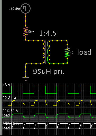
Hello All. I ordered a transformer for 48V input and 330V output. I want to know whether the provided values of the primary and the secondary inductances are okay or not? My primary current can go upto 21A. And the switching frequency is 100kHz, 1000W.
Attached is the document for the specs from the factory.
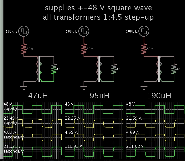
Also I want to know that if the actual inductance falls short of the required inductance, then what would be the outcome?
Thankyou in advance.
Attached is the document for the specs from the factory.
Also I want to know that if the actual inductance falls short of the required inductance, then what would be the outcome?
Thankyou in advance.