Continue to Site

Welcome to EDAboard.com

Welcome to our site! EDAboard.com is an international Electronics Discussion Forum focused on EDA software, circuits, schematics, books, theory, papers, asic, pld, 8051, DSP, Network, RF, Analog Design, PCB, Service Manuals... and a whole lot more! To participate you need to register. Registration is free. Click here to register now.

What is wrong with my inductive kickback oscillator

Status
Not open for further replies.

Resistanceisfutile

Member level 4
Joined
Aug 22, 2012
Messages
77
Helped
2
Reputation
4
Reaction score
1
Trophy points
1,288
Activity points
2,008
What is wrong with my oscillator?

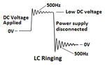
I'm aware inductive kickback occurs when the current through an inductor is rapidly changed.

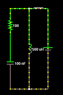
I connected a non-polar 0.10uF capacitor in parallel with a 500uH inductor to make a tank circuit and powered it using three 1.5v batteries. This should create a 500Hz pulse.
However, I hear no interference at this frequency which leads me to think it isn't working.

Is there some reason why my circuit wouldn't work - or is it likely I've just connected it up wrong?
 

LC in parallel fed with DC source => What pulse? You can get some sine wave by placing them in series.

LC in parallel theoretically works if there is no DC source (and one of them initially charged).

This is what you have done?
 
Last edited:

DC would quickly discharge through the inductor so C should be 'empty' at the time the voltage is applied.

Two things concern me:
1. when you say "I hear no interference", how are you listening?
2. what makes you think it will oscillate at 500Hz?

Brian.
 

You do not have an oscillator because there is no transistor or opamp to keep it going. Instead you have an LC that rings like a tapped bell.
The pulse activates it with power causing it to ring for a moment if the power is applied through a series resistor, then it rings again for a moment when the power is disconnected. It can feed an amplifier that has a high input impedance but then the output will have a loud POP when power through a series resistor applied to it then a louder POP and louder ringing when the power is disconnected.
 

Attachments

  • LC ringing.png
    LC ringing.png
    7.9 KB · Views: 87

It certainly can't sustain oscillation but the original post only refers to "a 500Hz pulse".
When the battery is applied it is unlikely it will 'ring' due to the damping effect of the battery itself and given the high current, the inductor will probably saturate anyway. When the battery is removed (if nothing smoked before hand!) it will 'ring' for a short time but at the natural LC resonance of a parallel tuned circuit.
1/(2*Pi* sqrt(LC))
= 1/(6.28 * sqrt(500e-6 * 100e-9))
= ~22.519KHz.

Brian.
 

I did not look at the parts values. I wonder why the calculation for the frequency produced a number that was 45 times too low?
 

Your calculations are wrong but the circuit is OK. You can also use series LC. Your setup is producing damped oscillation because there is no way to feed energy into the tank (energy must be supplied to the at the right time, I mean phase) but it is producing the pulse that you are unable to detect.
 

How a LC in parallel fed with DC supply works?

It is the classical analog of the spark gap transmitter.

If the switch is pressed too long, the battery is shorted. But during the time current builds up in the inductor and the capacitor is getting charged, oscillations will be produced.

When the switch is turned off, the oscillations start again.

if the switch is turned on and off at the right frequency and at the right time, we shall get a conventional oscillator.

Consider the simple Hartley oscillator: the job of the transistor is to turn on and off the power at the right time and it needs a feedback from the tank.

Consider your circuit in post #2. Take a tap from the inductor and put a transistor switch and you will have the Hartley oscillator.

If you put the L and C in series the circuit is not complete; to complete the circuit, you need to connect the free ends of the L and C and you will make them parallel. But if you connect the free ends of L and C to a battery, you will again get the same circuit but the potential is applied at different points. This still will not produce continuous oscillations because the timing is not given. We need a feedback from the tank and apply potential at right time and at the right place.

I hope I have made it clear. Sorry if I appear a bit vague. I am just trying to explain the process.

- - - Updated - - -

All it does is to quickly drain the battery. The very low internal resistance of the battery will prevent the LC from ringing.

It will still ring during the period the current is building up in the coil; it will again ring when the battery is disconnected. The oscillations will be damped because of internal resistance of the battery, coil and the capacitor.

I do not understand the simulation you have given in post #4.
 

In my post #4 I show the ringing of the LC when a DC voltage is applied to it through a resistor so the amplitudes of the DC and the ringing are reduced until the battery is disconnected then the ringing is at full amplitude.
 

Status
Not open for further replies.

Similar threads

Part and Inventory Search

Welcome to EDABoard.com

Sponsor

Back
Top