Continue to Site

Welcome to EDAboard.com

Welcome to our site! EDAboard.com is an international Electronics Discussion Forum focused on EDA software, circuits, schematics, books, theory, papers, asic, pld, 8051, DSP, Network, RF, Analog Design, PCB, Service Manuals... and a whole lot more! To participate you need to register. Registration is free. Click here to register now.

[SOLVED] Capacitor Transient Response Simulation in Proteus

Status
Not open for further replies.

ln30356

Newbie level 4
Joined
Jan 7, 2016
Messages
5
Helped
0
Reputation
0
Reaction score
0
Trophy points
1
Activity points
49
Hi everyone,
I 'm learning about Capacitor Transient Response, and I got problems in simulating in proteus.
I have a circuit in figure (a). At the time switching from open to close, there's a transient voltage at capacitor. I'm searching many way to get the graph described in figure (b), but not successfully. Can you tell me how I can get this from simulation in proteus?
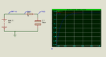
By the way, as simulating (figure (c)), at the first time, I realize that the voltage between capacitor plates is 15 V even the switch haven't been closed yet. It seems to me that the capacitor has been already charged. I don't get why that is. Can you explain this to me?
Thank you.

Figure (a)
2016-01-10_201405.png

Figure (b)
2016-01-10_195850.png

Figure (c)
2016-01-10_200014.png

Proteus file
View attachment AllaboutCircuit.rar
 

Try the attached simulation file. It is in Proteus 8.3 SP2 format.

You should not press simulation button at the bottom left. Instead you have to right click on the Graph and choose Simulate Graph.
 

Attachments

  • AllaboutCircuit.rar
    13.2 KB · Views: 163
I guess, specifying the switch closed at t = 0 means it's already closed at startup. Should specify a very small time offset.

Secondly minimum conductance constraints of the SPICE simulator might cause a problem in some cases. Adding a gohm leakage resistor the the capacitor might help.

Finally, check that the switch doesn't have a finite Roff value.
 

I think you have to change the capacitor model. I have used Animated Electrolytic Capacitor.
 

Attachments

  • Capacitor Transient Response.png
    Capacitor Transient Response.png
    13.2 KB · Views: 271
I think you have to change the capacitor model. I have used Animated Electrolytic Capacitor.
Thank you for your answer. I think the problem is that I chose the wrong capacitor. The circuit function as expected when I replace the capacitor. I still want to keep the button to see the result as described in figure (b) (of my last post), so I have to use the interactive analysis.

Thanks for your reply

2016-01-11_072851.png
 

In my circuit it has taken 400 ms to charge fully. So set the Oscilloscope timebase for 350 ms and use Oscilloscope to plot the graph.
 

In my circuit it has taken 400 ms to charge fully. So set the Oscilloscope timebase for 350 ms and use Oscilloscope to plot the graph.
Hi, thank for your suggestion.
I think the difference is that in first capacitor using case, the capacitor has been already charged at the first moment (figure a), while in second one, the capacitor has not been charged yet (figure b). By the way, can you tell me if there is any way to export value from the oscilloscope so that I can do some comparison with transient analysis?
Figure a
figurea.png

Figure b
figureb.png

Proteus
View attachment AllaboutCircuit.rar

Thank you.
 

You can save the oscilloscope output (graph) as a PDF file.
 

my proteus version is v8.1
and With its implementation does not change in interactive graph!!!
and just components change
please Once fully explain.
 

Status
Not open for further replies.

Part and Inventory Search

Welcome to EDABoard.com

Sponsor

Back
Top