Continue to Site

Welcome to EDAboard.com

Welcome to our site! EDAboard.com is an international Electronics Discussion Forum focused on EDA software, circuits, schematics, books, theory, papers, asic, pld, 8051, DSP, Network, RF, Analog Design, PCB, Service Manuals... and a whole lot more! To participate you need to register. Registration is free. Click here to register now.

problem with measuring rise time

Status
Not open for further replies.

elli

Junior Member level 3
Joined
May 3, 2015
Messages
26
Helped
2
Reputation
4
Reaction score
1
Trophy points
3
Location
IRAN
Activity points
192
i think things going to be very complicated here, so here is the exact question AND i will thank anyone who could help me out with this!
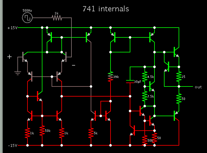
consider this LM741 in open loop with the specifications attached:(LTspice)
Capture.JPG
measure the rise and fall time of the output voltage with pulses with given amplitudes: +-5mv , +-5v , +-20mv
 

Attachments

  • LM741 (1).rar
    1.2 KB · Views: 75

The 741 opamp might be the oldest opamp still made and is one of the slowest. If the simulation model is accurate then it will be easy for it to measure rise and fall times.
 

Hi,

You asked about the same question some weeks ago.
https://www.edaboard.com/threads/348133/#post1486003

What is the new situation now?

Klaus

yes, actually i wanna attach the exact model, but there i cant, so i make this thread.
my problem still is what is the difference between these inputs? since i think with all of these inputs the output will get saturated! and the answer will be the same.
and my other problem is how to measure the slew rate of this opAmp? or any other opAmp specifically?
is there any topology which i can use to measure it in simulation?if there is no datasheet
and my other question is that: the slew rate is something related to the large signal behavior of the op_amp, so How this curcuit work with such an small signals like +-5mv ?

thank you all by helping me, again
 

Internal schematic of a 741 op amp. This is found in the 'Circuits' menu of Falstad's simulator.


www.falstad.com/circuit

I'm not sure that the transistors model propagation delay, Miller effect, etc.

One capacitor is visible. Its value influences the slew rate in the simulation. We can surmise it is a factor in hardware as well.
 
  • Like
Reactions: elli

    elli

    Points: 2
    Helpful Answer Positive Rating
5mV is a HUGE signal level to an open-loop opamp. The old 741 opamp has a typical open-loop voltage gain of 200,000 so with a plus and minus 15V supply its output is saturated when its input is only 14V/200,000= 70uV. Its output slews at typically 0.5V per us.
 
  • Like
Reactions: elli

    elli

    Points: 2
    Helpful Answer Positive Rating
I don't understand which problem this thread is talking about. You are showing a simulation circuit and the macro model provided by National Instruments. What are the simulation results? Which problem do you face?

It's true that 5 mV can be expected to achieve output saturation. But it doesn't steer the input stage to drive maximum current into the miller capacitor and thus the OP does not reach full slew rate. That's the sense of using different input voltages in the exercise problem.
 
  • Like
Reactions: elli

    elli

    Points: 2
    Helpful Answer Positive Rating
Status
Not open for further replies.

Part and Inventory Search

Welcome to EDABoard.com

Sponsor

Back
Top