Continue to Site

Welcome to EDAboard.com

Welcome to our site! EDAboard.com is an international Electronics Discussion Forum focused on EDA software, circuits, schematics, books, theory, papers, asic, pld, 8051, DSP, Network, RF, Analog Design, PCB, Service Manuals... and a whole lot more! To participate you need to register. Registration is free. Click here to register now.

Charge pump and single pulse creator, how to?

Status
Not open for further replies.

neazoi

Advanced Member level 6
Joined
Jan 5, 2008
Messages
4,123
Helped
13
Reputation
26
Reaction score
15
Trophy points
1,318
Location
Greece
Activity points
36,955
Hello I am making a special type of indicator to find my keys on the darkness.
Usually Tritium-based indicators would be used but I do not want to do so.

The solution I found was to use a hybrid system. Glow-in-the-dark pigment (my best one) combined with a UV LED to light it up.
A gravitational switch detects when the keys have been moved (when searching them in the wallet/bag for example) and sends a pulse of power at the LED.
This works great for me.

1. However, what I need to do, is somehow detect when a pulse comes from the switch and light up the LED. Then for some time (seconds) do not light up the led, even if a second pulse comes.
This will save battery life a lot. The detection circuit must draw very very little power to prolong the small button cell (AG1) battery life.

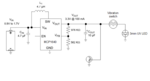
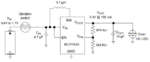
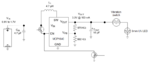
2. Also a suitable charge pump IC is needed to step up the voltage from 1.2-1.5v (button cell) to 3-3.2v. I could use just two batteries in series, but if very low power IC exists, then a one-battery booster can be made. only a short period pulse is needed. Any ideas for such a low power IC?

- - - Updated - - -

TPS61260 as a boost up converter, seems good?
 
Last edited:

I imagine you want to use a ready-made IC, otherwise I'd have suggested a capacitor(s) and diode(s) combination, or maybe RC, or that Joule-thief circuit.

...that's the name..."Cockcroft-Walton voltage multipliers", chuckey mentioned it in this thread:

https://www.edaboard.com/threads/347368/
 
Last edited:
  • Like
Reactions: neazoi

    neazoi

    Points: 2
    Helpful Answer Positive Rating
I imagine you want to use a ready-made IC, otherwise I'd have suggested a capacitor(s) and diode(s) combination, or maybe RC, or that Joule-thief circuit.

I do not care. It is only a matter of efficiency. The tps61260 states an efficiency of 95%. Similar is the mcp1640. However at 0.8v efficiency drops to 80%. I do not know how the joule thief does in terms of efficiency.
Powering the circuit from a single AG1 cell (SR621SW) must require an efficient booster.
Although the circuit will be powered only when the vibration switch closes.

The most difficult part is not the booster, but the single pulse (and then prohibit for some time) circuit I mention above. I have no idea how this could be done.
 
Last edited:

I can only think of RC and using time it takes capacitor to charge for the delay, I suspect not a good method for what you are doing. I've given up on a 0 - 100Hz frequency to voltage converter as it seems impossible at such low frequencies, and I can't count or control electrons trickling here at home, whatever reliable circuits I copy or time constants I read about :)

From the datasheets I read for boost converters, etc. , most seemed much of a muchness, nothing is ideal (bitter-sweet joy of putting a circuit together, eh), and 80% is pretty good, isn't it? I'd probably go with that one and use time saved searching or messing around experimenting with things that are far from ideal for other parts of circuit, or other things.
 
  • Like
Reactions: neazoi

    neazoi

    Points: 2
    Helpful Answer Positive Rating
I can only think of RC and using time it takes capacitor to charge for the delay, I suspect not a good method for what you are doing. I've given up on a 0 - 100Hz frequency to voltage converter as it seems impossible at such low frequencies, and I can't count or control electrons trickling here at home, whatever reliable circuits I copy or time constants I read about :)

From the datasheets I read for boost converters, etc. , most seemed much of a muchness, nothing is ideal (bitter-sweet joy of putting a circuit together, eh), and 80% is pretty good, isn't it? I'd probably go with that one and use time saved searching or messing around experimenting with things that are far from ideal for other parts of circuit, or other things.

This patent seems interesting.
It uses the boost converter not to directly power the LED, but to charge a capacitor. Then the capacitor could power the led through the vibration switch and get's discharged gradually.

If I could fed the capacitor (through a resistor voltage divider??) to a small mosfet gate (for low loading) then I could use this mosfet as a switch to switch a second mosfet and this second mosfet for supply the power to the converter (the two mosfets will act as an inverted switch). The second mosfet drain would be connected to the battery and the sourse to the converter (or the other way round?)

This would switch the converter off, when the capacitor is charged above a threshold voltage, so that the converter does not draw any power when the capacitor is charger.
When it gets discharged the cycle will repeat again.
How does it sound?
 

Attachments

  • US20120256595.pdf
    409.2 KB · Views: 126

...it sounds complicated, but could work... Do you mean a high-side switch where the driver MOSFET gate is controlled by the same capacitor that will feed the LED, so the converter is on until the cap is charged, which will pull the driver MOSFET high (i.e. off); and when activated by the gravitational switch trigger signal, the cap will discharge into the LED, and by being discharged start the cycle again by pulling the MOSFET gate low and begin recharging the capacitor via the converter?
 
  • Like
Reactions: neazoi

    neazoi

    Points: 2
    Helpful Answer Positive Rating
...it sounds complicated, but could work... Do you mean a high-side switch where the driver MOSFET gate is controlled by the same capacitor that will feed the LED, so the converter is on until the cap is charged, which will pull the driver MOSFET high (i.e. off); and when activated by the gravitational switch trigger signal, the cap will discharge into the LED, and by being discharged start the cycle again by pulling the MOSFET gate low and begin recharging the capacitor via the converter?

Yes, exactly this.
A little bit of experimentation is needed though with the mosfet gate thresholds.
For example, how should I ensure I will not overdrive the mosfet gate to destruction when it is on and how should I provide lowest voltage threshold from the capacitor to the gate, when it should be switched to off (a gate series zener?)

- - - Updated - - -

Yes, exactly this.
A little bit of experimentation is needed though with the mosfet gate thresholds.
For example, how should I ensure I will not overdrive the mosfet gate to destruction when it is on and how should I provide lowest voltage threshold from the capacitor to the gate, when it should be switched to off (a gate series zener?)

I have just read the mcp1640 datasheet. It has a disable pin, which is more convenient to use (and avoids transistor switch voltage drop). In the disable mode it consumes 2.3uA max. I think this is a very tiny fraction that won't affect the button battery life if left for a long time ( 2-3 years or so?)

What do you think about it?
 

Hi,
Thanks for explaining. The Zener (they're useful but energy wasters I think) with a small? series resistor isn't a bad idea, or could it work in parallel to the gate to control max. input voltage when conducting?

What I've discovered over the past few days is that capacitors aren't linear, charging or discharging (the 1T = 63% or 1T = 37% thing), which for me at least makes them difficult to implement where a linear response is needed/wanted... Shame as they are so useful and easy to use in many other ways.

I love enable/disable pins they make certain functions a lot simpler, knowing that is available I'd choose the mcp1640 probably. I was thinking before, and not knowing much, regarding space/size and simplicity of implementation (not to say experimentation time to ensure reliable operation consistently), I'd choose the IC over the other ideas so far, - look at that: 2.3uA max, delightful.
 
  • Like
Reactions: neazoi

    neazoi

    Points: 2
    Helpful Answer Positive Rating
Hi,
Thanks for explaining. The Zener (they're useful but energy wasters I think) with a small? series resistor isn't a bad idea, or could it work in parallel to the gate to control max. input voltage when conducting?

What I've discovered over the past few days is that capacitors aren't linear, charging or discharging (the 1T = 63% or 1T = 37% thing), which for me at least makes them difficult to implement where a linear response is needed/wanted... Shame as they are so useful and easy to use in many other ways.

I love enable/disable pins they make certain functions a lot simpler, knowing that is available I'd choose the mcp1640 probably. I was thinking before, and not knowing much, regarding space/size and simplicity of implementation (not to say experimentation time to ensure reliable operation consistently), I'd choose the IC over the other ideas so far, - look at that: 2.3uA max, delightful.

My circuit so far looks like this.
There must be a way to detect a lower threshold on the capacitor (eg 2.8v), without loading it too much, and then connect the enable pin into vin, to recharge the capacitor.

The goal is not to load the capacitor much to avoid discharging it.
Any ideas?
 

Attachments

  • circuit.PNG
    circuit.PNG
    26.1 KB · Views: 138
Last edited:

Hard for me... All I can think of now, and it seems OTT, and probably wouldn't work, is a comparator across the 10uF terminals, so when it is fully charged the comparator goes low, and pulls enable low, and when the capacitor is discharged the comparator goes high and pulls enable high long enough for it to charge. I do not think this would work very well, maybe it can in the right hands, but sounds like a high precision tiny measurement comparison and how much current would the comparator use whilst monitoring...
This seems less parts than a comparator into an inverter controlling enable.
 

There used to be (maybe still is) a cute little special
function IC from National, a LED flasher that would
work off one cell. LM3909? Anyway, this was a simple
1-stage capacitor charge pump meant for sparse pulse
operation. While the UV-LED / phosphor scheme seems
neat, you will need a higher voltage than a red LED.
On the other hand a modern lithium cell could direct
drive visible LEDs and you need the barest flash to
make it visible. Like a millisecond at 1Hz, would be fine.
Might be that flashing is better for finding stuff, than
CW illumination anyhow (especially if behind some
other object).
 

Is connecting the vibration sensor to the enable input a viable solution? Maybe with a capacitor to lengthen any pulses it produces.

I use a discrete component design that mimics the LM3909 to flash LEDs to mark the edges of paths here as it is totally dark at night. I use a single 1.2V rechargable AA battery and a small PV panel to recharge it and inhibit the flashing during the day. It is one of my more 'over designed' projects as a while ago while building works were carried out, they were all put in storage inside boxes (hence dark all the time). When the box was opened 5 months later they were all still happily flashing!

Brian.

Interesting, but the point is to keep the AG1 (tiny size and weight important) button battery running for a few years not months. This device has to compete with Tritium devices, in a more safe way for the carrying person. This means that the circuit must not continuously operate at any means.
If I put the vibration switch just after the battery and then the charge pump and finally the led, that would simply do the trick and the circuit will be activated only by vibration. At off-state the only source of current draw is the internal resistance of the battery and the silver oxide type I use has very low self discharge and it's voltage stays relatively consistent throughout it's life, then suddently drops towards the end of it's life.

However, I was wondering if battery can be preserved even more by having only the first pulse light up the led, then at the second pulse the power to the circuit will cut-off for some time, before it is allowed again.
This would save battery in cases where continuous vibration exist, like inside a pocket when running.
The single UV led pulse is enough to excite my glow-in-the-dark pigment for hours.

I was trying to think of an ingenious passive circuit to do so (relay? other type of switch that stacks for a while? even a mechanical timing switch of some kind), as all "active" devices consume power.
 
Last edited:

The battery/vibration switch/charge pump/led combination I was talking about.

Can anyone think of any mechanism placed on the vibration switch side that can switch off the charge pump (EN pin low, of completely cut off the Vin)?
Maybe a mosfet with it's gate connected to the input capacitor? Or any other mechanical delay device?
 

Attachments

  • circuit.PNG
    circuit.PNG
    23.9 KB · Views: 132
Last edited:

Hi again, back from the comparator marketing board :) I was thinking about it, and when I remembered the output side is 3.3V (not ~1V) , I see no reason not to use a comparator powered directly from the battery to detect the capacitor voltage, when it is charged to enable or disable the converter. Could use two, but too much board space probably, to turn on at <x threshold, and another to turn off enable at >3.3V. Triggers on at either ~3.3V or off at ~0.5V just to say a number to work from.
Are there high-speed, rail-to-rail comparators with low quiescent current? I imagine there are.
Your thought is helpful, but I am mostly considered post #14 as it seems a less power hungry circuit. After all what is the point (in terms of power efficiency) of keeping the output capacitor charged and cut-off the charge pump? Just totally cut off the power as on post #14.

So the question remains, a mechanism for post #14 circuit, that after the first pulse (or a few pulses until a capacitor is charged) from the vibraswitch comes, would either:
1. Block the Vin power for a few seconds
2. Or make the EN pin low for a few seconds

This is all that is needed
 

Basically, what you need is the best compromise between low current consumption and circuit complexity, given that more complex designs may be more verstile but also use more power.

I don't think the circuit in post #14 will work well, the reason is conceptual, the charge pump has to raise the output voltage to at least twice the input voltage and if follows that the current needed to charge the output capacitor has to come from the input capacitor which is only half it's value. The input capacitor would need to be at least twice (and probably a lot higher) value that the one across the LED. That produces a further problem, the inrush current to charge the input capacitor will almost certainly be magnitudes higher than the vibration sensor is rated for.

I've lost the schematic for the design of flasher I made but it has an inhibit input so it may still be of use to you. It's a simple design using only a few discrete components and I have a spare one somewhere. I'll look for it later and trace the schematic again for you. If I remember correctly, it uses a three transistor oscillator which might be able to work in monostable mode, in other words it you trigger it once from your sensor, it would produce one flash of light from the LED then go back to sleep. I think that's what you are trying to build.

I remember running an LM3909 flasher in a fake burglar alarm unit for more than one year from a single AAA cell so it is possible to do.

Brian.
Yes please post the schematic if you find it.
A monostable operation will achieve that I need yes, thank you.
However the power to the monostable needs to be constant. In other words, if the power comes from a vibration sensor, a capacitor has to be charged first, to power this monostable. Else, each time the vibraswitch is activated the monostable would pulse anyway.

The power rating of the vibraswitch you mention worries me. The LED draws 20mA at 3v (typical for high brightness LEDs). Do you think the initial current drawn from the charge pump will be much greater? I was actually thinking of totally removing the input capacitor for a faster pulse, the datasheet states that it could be done, although not recommended.

Hm... look at the first circuit in this page https://www.electronics-tutorials.ws/waveforms/monostable.html a single fet could to the job easy (and less power hungry?)
 
Last edited:

The current will be significantly higher for a few cycles and the circuit relies on a low input impedance, if you remove the capacitor the ESR of the cell will play a big part in circuit efficiency and tiny cells have a big ESR! Remember that you are trying to double the voltage to the LED and even if the circuit was 100% efficient, you would have to double the input current to achieve that.

The FET design won't work i'm afraid, firstly it needs the supply to be higher than the LED forward voltage and the knee voltage of the FET, secondly - works in reverse! the LED lights when the switch is opened, not closed!

Brian.
 
  • Like
Reactions: neazoi

    neazoi

    Points: 2
    Helpful Answer Positive Rating
The current will be significantly higher for a few cycles and the circuit relies on a low input impedance, if you remove the capacitor the ESR of the cell will play a big part in circuit efficiency and tiny cells have a big ESR! Remember that you are trying to double the voltage to the LED and even if the circuit was 100% efficient, you would have to double the input current to achieve that.

The FET design won't work i'm afraid, firstly it needs the supply to be higher than the LED forward voltage and the knee voltage of the FET, secondly - works in reverse! the LED lights when the switch is opened, not closed!

Brian.

I am trying to fool the thing a bit, This is an incomplete schematic.
 

Attachments

  • circuit2.PNG
    circuit2.PNG
    26.8 KB · Views: 127

Status
Not open for further replies.

Part and Inventory Search

Welcome to EDABoard.com

Sponsor

Back
Top