Continue to Site

Welcome to EDAboard.com

Welcome to our site! EDAboard.com is an international Electronics Discussion Forum focused on EDA software, circuits, schematics, books, theory, papers, asic, pld, 8051, DSP, Network, RF, Analog Design, PCB, Service Manuals... and a whole lot more! To participate you need to register. Registration is free. Click here to register now.

periodic ripples on the control voltage of oscillator

Status
Not open for further replies.

hanikapa

Member level 4
Joined
Feb 6, 2015
Messages
71
Helped
0
Reputation
0
Reaction score
0
Trophy points
6
Activity points
510
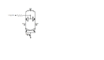
I have designd a usual LC oscillator that is controlled by applying voltage to NMOS varactors. When I put a resistance between control voltage and varactors, I see there are periodic ripples on the varactor node. The importance of this point is that I use the VCO in PLL and this ripples in PLL creates more noise. Does anybody knows if these ripples on the control voltage of LC VCO is natural? What should I do to remove them?
Thanks
 

here is the schematic. I see the periodic ripples at MOS varactor nodes.
 

Attachments

  • vco.png
    vco.png
    32.2 KB · Views: 124

I think it would be helpful if you could measure the period of the ripple. It might be an idea to break the PLL loop and feed the oscillator from a PSU which would remove any PLL instability, but not RF instability.
Frank


The period of ripple is about 100KHZ and the oscillation frequency of oscillator is 4GHz. The point is here that without putting the VCO in PLL and just by applying the dc control voltage the ripples exist on varactor node. I think first I should solve the problem for VCO itself, then it will not have problem in PLL.

- - - Updated - - -

It seems you can not understand my append in the following at all.
https://www.edaboard.com/threads/345764/

Attach capacitor to varactor node.
Then design 3rd order loop filter.

I did this 3rd order loop filter idea , it will reduce the amplitude of ripples but it will not change the ripples frequency and do not remove the ripples.
 

I have a feeling that the circuit wants to go off as a multivibrator, using the resistance of the drain inductors as its load. Try floating the Vdd by feeding it via a resistor, as the RF currents are out of phase it should not effect them, but put in voltage negative feed back at LF.
Frank
 

The signals at outp, outn, varactor node and control voltage
 

Attachments

  • waves.png
    waves.png
    29.5 KB · Views: 109

The period of ripple is about 100KHZ
and the oscillation frequency of oscillator is 4GHz.
Frequency of varactor node is twice of oscillation frequency(=frequency of OUTP and OUTN).
This is condradictory to the description you wrote in #6.

From waveform you showed, ripple on varactor node is due to leakage of oscillation(OUTP and OUTN).

By the way, what simulator do you use ?
Show me steady state anlysis results for varactor node, OUTP and OUTN.

If you mean 100kHz ripple as envelope of varactor node, show me result of steady state analysis such as Harmonic-Balance or Shooting-Newton.
 
Last edited:

I use spectreRF.
the results that I showed is the result of transient analysis.
what do you mean by steady state analysis please?
 

I use spectreRF.
the results that I showed is the result of transient analysis.
what do you mean by steady state analysis please?
Autonomous Harmonic-Balance or Autonomous Shooting-Newton.

Waveforms is contradictory to descriptions you wrote in #6.
 

Sorry, you are right. The frequency of ripples on varactor node is about twice of the oscillation frequency.
 

Status
Not open for further replies.

Part and Inventory Search

Welcome to EDABoard.com

Sponsor

Back
Top