Continue to Site

Welcome to EDAboard.com

Welcome to our site! EDAboard.com is an international Electronics Discussion Forum focused on EDA software, circuits, schematics, books, theory, papers, asic, pld, 8051, DSP, Network, RF, Analog Design, PCB, Service Manuals... and a whole lot more! To participate you need to register. Registration is free. Click here to register now.

[moved] CMOS logic selection

Status
Not open for further replies.

Mutad0r

Junior Member level 3
Joined
Feb 13, 2013
Messages
28
Helped
0
Reputation
0
Reaction score
0
Trophy points
1,281
Activity points
1,608
So I'm making a processor just for the fun of it and in various situations I will have to select between outputs, for example, should the output signal be from the full adder, a logic shift or whatever else the processor has. I'm not entirely sure how to implement this.

At first glance you could use an AND gate to sort of "enable" a signal to pass through, but the problem is that a CMOS logic gate actively pulls the output to ground if it's set to 0. This is demonstrated in the following image.
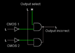
Cmoses.png

I haven't gotten a solution to this so far, so halp.

What I basically need is to have a gate that allows the digital signal to pass through, but otherwise lets the output float freely, without pulling it up or down.
 

I think what you are looking for is a multiplexer and not some "wired AND" logic.

A two input multiplexer would have the following logic:
Code:
o = (s AND a) OR (!s AND b)
 
After reading about multiplexers, I suspect you're right. I had hoped that it would be a bit simpler, because a multiplexer uses a lot of logic gates and I intend on making the processor without any ICs ( I have estimated it to use thousands of MOSFETS .. :D )
 

I have estimated it to use thousands of MOSFETS

ergo, that is why there are 1.4 billion transistors on an i7 processor. It's also why processors aren't designed at the transistor level but are designed using a hardware description language and then translated (ssynthesized) to gates in a library, which has the transistor layout information in them.

If you want to design a processor I strongly suggest you use Verilog or VHDL and write a hardware description of the processor instead of trying to create one using discrete MOSFETS. Doing what you are attempting won't develop any real world useful skills.

But if you insist on doing this you'll want to stick to no more than a 4-bit processor design, otherwise the transistor count will be in the 10's of thousands instead of 100s. Are you aware that Verilog has transistor models and weak 1s and 0s, so you can model a transistor level digital circuit. Instead of making a huge breadboad with 1000's of MOSFETS you might want to do it in Verilog and run a simulation instead. I'll admit I've never tried using that feature of the language, so you're on your own.
 

What I basically need is to have a gate that allows the digital signal to pass through, but otherwise lets the output float freely, without pulling it up or down.

This sounds as though you want a tri-state device. Example, 74LS367, 74LS368.

It has an Enable pin. You pull it low to make the output pin match the input.
Pull it high to make the output go to hi-impedance.

- - - Updated - - -

These IC's are known as '3-state bus drivers'.

There is a circuit where they are used as a 1-of-2 data selector.
 

ergo, that is why there are 1.4 billion transistors on an i7 processor. It's also why processors aren't designed at the transistor level but are designed using a hardware description language and then translated (ssynthesized) to gates in a library, which has the transistor layout information in them.

Sounds reasonable that a person hasn't designed these at the hardware level. You're right to question the usefulness of making a processor on the transistor level, and I suppose you're right. The work I've done so far has taught me a lot about different types of logic gates and how they are made, but after that, it would just be a bragging point. I have currently made a full bit adder using 62 SOT-23 package transistors on a single sided board (about 50x20mm in size)

I might switch over to using logic gate IC-s to make a simple processor, but I think I will make it either way, without using any fancy programs, because I believe that there's still quite a bit to learn from it. (plus, it's a bragging point in itself, transistors or not)

Afterwards, I might just look into those fancy programs you mentioned.

Also, who in their right mind would make a processor of thousands of transistors on a breadboard? :D I was going to make the circuit using proteus, run a simulation of it, to make sure it works and then have the board made and assembled with a pnp machine somewhere else.
 

The basic building block is a register or FlipFlop (FF) and the fundamental parts of these are transmission Gates that are Tri-state outputs as several are used in each FF.

It could stretch your budget and time demands.
 

If you want to design a processor I strongly suggest you use Verilog or VHDL and write a hardware description of the processor instead of trying to create one using discrete MOSFETS. Doing what you are attempting won't develop any real world useful skills.

It's not necesary. For a very very basic processor you have to do all combinational circuits for the operation you want, add, compare , multiply ( why not ) , etc. All operation takes the data (binary word) from 2 register (for example) and this has a number of bit. The register are flip flop (types D).

There is a register (PointerCounter-PC) which has the value of the memory location that procesor will read (put in same register), very times it's read this register increase (a lot of procesor allow chages the register's value whit same instruction). The register(PC) bits are put on the address bus.

The operation has to be like this. The first data is an opcode, which has the type of operation you want to do and the registers you are going to use (to allows them for the two next movements), an put it on a register (responsible for the instructions for later to decode it ) the other two data has to be the values, operators. When the procesor has every thing in the register, it decode the instruction, whit a decode ofcourse and it allow the corresponding combinational circuit will operate with 2 register where the data was stored and then save it to another , or in memory.

As register are flip flop there must be a synchronism, between the data move.

That's the basic, you do not have to learn about VHL but if you want to do a big thing, yes.

What does any of the above have to do with my recommendation that the OP use VHDL/Verilog to describe the processor design?

Using VHDL/Verilog or an even higher level C-gates type methodology is how processors are designed today, using MOSFETs like the OP was going to do is circa mid 1970s 8080, Z80, etc days of processor design. If you want to have skills that are applicable today then you learn VHDL/Verilog. Maybe having an antiquated skill set will get a job maintaining some obscure one of a kind system that the owners are too cheap to upgrade, but it sure isn't going to give you a career in engineering the next generation of processors.

- - - Updated - - -

Interesting chart of microprocessors and the process nodes they were on. https://en.wikipedia.org/wiki/Microprocessor_chronology.

Note the OP should stick with processor architectures like those that are pre-1975 preferably something in the 4-bit category like a 4004, which would only require a few thousand transistors. Don't expect much more than a few 10s of KHz clock frequency on that humongous discrete processor board.

Instead of making an actual board, why don't you just build this in Minecraft? I'd actually be more impressed if you did that than an actual circuit board. Plus you'll get all the kudos from other Minecraft aficionados, but based on this or this you'll probably have to build a 64-bit multi-threaded multi-core processor design to really impress everyone. ;-)
 

What does any of the above have to do with my recommendation that the OP use VHDL/Verilog to describe the processor design?
Yes you are right, but I did not say don't use or learn VHDL, I just said it's not necesary at basic level.

If you want to have skills that are applicable today then you learn VHDL/Verilog. Maybe having an antiquated skill set will get a job maintaining some obscure one of a kind system that the owners are too cheap to upgrade, but it sure isn't going to give you a career in engineering the next generation of processors.
you are right again but, if someone start, to have a complete knowledge need the basic. If you see what I said it's VHDL but whitout the code, only common words. In addition , an engineer should be able to express in simple words what makes clear that not only communicates with other engineers. In a basic level, VHDL it's a program language with "time", synchronism.
 

Status
Not open for further replies.

Part and Inventory Search

Welcome to EDABoard.com

Sponsor

Back
Top