Continue to Site

Welcome to EDAboard.com

Welcome to our site! EDAboard.com is an international Electronics Discussion Forum focused on EDA software, circuits, schematics, books, theory, papers, asic, pld, 8051, DSP, Network, RF, Analog Design, PCB, Service Manuals... and a whole lot more! To participate you need to register. Registration is free. Click here to register now.

Discrete frequency to voltage converter?

Status
Not open for further replies.

neazoi

Advanced Member level 6
Joined
Jan 5, 2008
Messages
4,123
Helped
13
Reputation
26
Reaction score
15
Trophy points
1,318
Location
Greece
Activity points
36,955
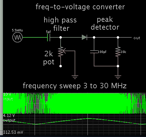
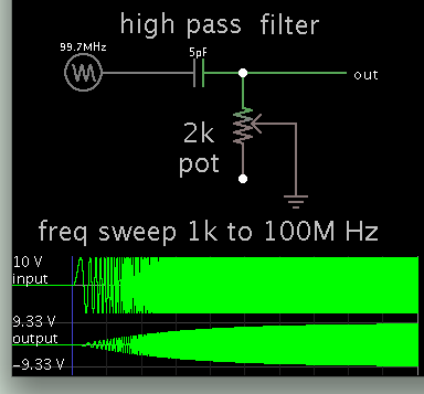
Is there any way to build a simple frequency to voltage converter for HF?
Discrete components way is preferred, if possible.

I will be using this in a AFC system to correct the frequency of an LC oscillator.
 

Some time ago i have seen paper or patent on frequency correction scheme using diplexer. Signal was splitted to two lines with band-pass filters F1 and F2. Output of each filter was conected to detector diode. Comparing voltage level on both diodes it is possible to determine if input frequency is closer to F1 or F2 frequency. All schematic was analog transistors, capacitors, resistors and microstrip filters. Output was voltage for varcator tuned microstrip VCO. I think at lower frequencies microstrip filters can be made lumped.

- - - Updated - - -

Also i remember that bandpass filters was not very narrow, with overlaping bandwidths. And maybe there was an opamp somwhere in the scheme. At GHz frequencies such scheme provided frequency control without using expensive prescaler ICs. But in your case i am not sure if it can be useful, i mean lumped filters must be stable with temperature, better than lc oscillator...
 

Here is a simple F-to-V converter.

High-pass RC filter, followed by a peak detector.

Component values were adjusted so the slope is most pronounced in the HF band, 3 to 30 MHz.


It draws a few mA. By adjusting component values, you can obtain reasonably linear response.
 
  • Like
Reactions: neazoi

    neazoi

    Points: 2
    Helpful Answer Positive Rating
Here is a simple F-to-V converter.

High-pass RC filter, followed by a peak detector.

Component values were adjusted so the slope is most pronounced in the HF band, 3 to 30 MHz.


It draws a few mA. By adjusting component values, you can obtain reasonably linear response.


The AFC systems I have seen (attached) use mixers to do the stabilization.
I thought that if I could have a frequency to voltage converter, then I could do this much simpler.

I never thought it would be that simple, as you propose!
How does your circuit actually work, can you say a few words about it's operation?
 

Attachments

  • qexfeb96.pdf
    818.7 KB · Views: 143

maybe capacitor on output discharges through resistor, half sine on input charges it, so for different half sine freq we have different charging of capacitor vs time, while discharging is controlled by resistor which is unchanged. This scheme maybe sensitive to output power of oscillator also
 
  • Like
Reactions: neazoi

    neazoi

    Points: 2
    Helpful Answer Positive Rating
The PA0KSB schematic is a variant of the well known huff & puff VFO stabilizer. They are simple to build, works well, but unfortunately phase noise is ridiculous high. Anyway, is a good option for a low cost VFO stabilizer.
I think the diode peak detector from above needs more decoupling capacitors at the output in parallel to get a flat DC response vs frequency (like 100pF, 1nF, 10nF, 100nF). Also the input cap (5pF) needs to be changed to about 1nF.
 

I never thought it would be that simple, as you propose!
How does your circuit actually work, can you say a few words about it's operation?

The high-pass filter works automatically to emphasize higher frequencies. (Assuming the input is constant amplitude.)


The idea is to tune the RC network, to adjust the rolloff curve so it is in your desired frequency range. You can use a larger capacitor, but then you need to reduce R, which draws greater Amperes from your source.

By adding a diode, it becomes a detector of Amplitude Modulation.

To put the two together, was a case of looking at something enough times, and realizing there might be potential for a useful application.
 
  • Like
Reactions: neazoi

    neazoi

    Points: 2
    Helpful Answer Positive Rating
The high-pass filter works automatically to emphasize higher frequencies. (Assuming the input is constant amplitude.)


The idea is to tune the RC network, to adjust the rolloff curve so it is in your desired frequency range. You can use a larger capacitor, but then you need to reduce R, which draws greater Amperes from your source.

By adding a diode, it becomes a detector of Amplitude Modulation.

To put the two together, was a case of looking at something enough times, and realizing there might be potential for a useful application.

Ah, I see what you do! You rely on the filter response curve, frequency (X-axis) and attenuation (Y-axis). Because the filter is of very low order, it has a relatively broadband decaying response, that covers well the HF bands.
Then you just detect the output voltage using an envelope detector.
Of course this assumes that the input signal to the filter is constant.

Have I understood that right?

I also have a question on this. How accurate is it? I.e. is the output voltage step size enough every say 10Hz or so, so that this change can be detected adequately by a voltmeter?
 

Hm... I have found that it can also be done with a ratio detector as well.
However I have not found a wideband ratio detector, all the schematics I see are for fixed IFs.
The circuit is more complex also...
 
Last edited:

Ah, I see what you do! You rely on the filter response curve, frequency (X-axis) and attenuation (Y-axis). Because the filter is of very low order, it has a relatively broadband decaying response, that covers well the HF bands.
Then you just detect the output voltage using an envelope detector.
Of course this assumes that the input signal to the filter is constant.

Have I understood that right?

Yes, that's how it works.

I also have a question on this. How accurate is it? I.e. is the output voltage step size enough every say 10Hz or so, so that this change can be detected adequately by a voltmeter?

10 Hz is 1 ppm in a 10 MHz signal. It is a tall order to ask for that degree of precision.

Theoretically, it is possible to adjust values so you get, say:
1V output at 10 MHz input, and
2V output at 20 MHz input.
Then in that case, a 10 Hz change yields 1 uV difference.

I suppose it is possible to make the smoothing capacitor a large enough value to minimize ripple, allowing you to measure 1 uV. Again, it's a tall order to fill.
 
  • Like
Reactions: neazoi

    neazoi

    Points: 2
    Helpful Answer Positive Rating
Yes, that's how it works.


10 Hz is 1 ppm in a 10 MHz signal. It is a tall order to ask for that degree of precision.

Theoretically, it is possible to adjust values so you get, say:
1V output at 10 MHz input, and
2V output at 20 MHz input.
Then in that case, a 10 Hz change yields 1 uV difference.

I suppose it is possible to make the smoothing capacitor a large enough value to minimize ripple, allowing you to measure 1 uV. Again, it's a tall order to fill.

I have figured out that my oscillator can be tuned directly by just adjusting the potentiometer (i.e. the filter slope). This way you move the slope up or down to the frequency axis and the oscillator follows this movement and try to correct it's frequency. Of course in your HPF it is not possible, because of accuracy problems, as I suspected, because it has a slowly decaying curve.

But if the filter was more sharp, then it's side slope would be more angled. This slope would cover a smaller amount of frequencies, (say 1MHz or so, even smaller, if filter is steep) and it would need readjustment for another set of frequencies. But in my case, I need the oscillator to be tuned, so this is perfectly fine with me.

The problem is that I do not have a tool to design RC HPFs and I do not want to use LC.
Can you help me design a more sharp (the sharpest the better) tuneable RC HPF fot HF?

Cheers
 
Last edited:

Theoretically, it is possible to adjust values so you get, say:
1V output at 10 MHz input, and
2V output at 20 MHz input.
Then in that case, a 10 Hz change yields 1 uV difference.

The only "little" difficulty is that the oscillator amplitude variation over the frequency must be much less than this. How realistic is that?

- - - Updated - - -

and I do not want to use LC.

Why? With LC you get twice the slope sharpness, and fixed value inductors can be purchased for a few cents.
 
  • Like
Reactions: neazoi

    neazoi

    Points: 2
    Helpful Answer Positive Rating
The only "little" difficulty is that the oscillator amplitude variation over the frequency must be much less than this. How realistic is that?

- - - Updated - - -


Why? With LC you get twice the slope sharpness, and fixed value inductors can be purchased for a few cents.

For your first point, the oscillator uses an AGC so I do not think there will be a huge problem in amplitude variations.
For the second point, I am thinking it this way:
What is the point of using an LC HPF to stabilize an LC oscillator? I mean the same ammount of thermal drift applies to both the filter L and the oscillator resonator L. It is like a cat trying to catch it's tail. I may be wrong though, correct me on this.
However you are right, I get a much better and sharp response with just an L and two C configured as a HPF
From an online calculator I found the slope of your RC to be very linear.
 
Last edited:

For your first point, the oscillator uses an AGC so I do not think there will be a huge problem in amplitude variations.

How good is that AGC? With your concept, even the smallest 0.00x dB amplitude change would cause a big frequency change.

For the second point, I am thinking it this way:
What is the point of using an LC HPF to stabilize an LC oscillator? I mean the same ammount of thermal drift applies to both the filter L and the oscillator resonator L.

I agree that it doesn't make much sense. But with RC, it is even worse. You replace the good stability of LC oscillator with the bad stability of RC.

To me, this whole idea looks wrong by design. Simple but terrible in results.
 
  • Like
Reactions: neazoi

    neazoi

    Points: 2
    Helpful Answer Positive Rating
How good is that AGC? With your concept, even the smallest 0.00x dB amplitude change would cause a big frequency change.


I agree that it doesn't make much sense. But with RC, it is even worse. You replace the good stability of LC oscillator with the bad stability of RC.

To me, this whole idea looks wrong by design. Simple but terrible in results.

How about a ratio detector?
I have not seen a broadband design though. Ok, the solution is to use a mixer to bring it to an IF.

I think that again, the tuned LC in the ratio detector will do not good because of the thermal stability issues described above. Also ratio detectors are used to detect relatively narrow FM deviation, so I doubt how can I use it for the whole HF band.
 

Why would that be useful for an unmodulated single carrier?

It is all about AFC. The ratio detector can be used as a AFC device as well, converting frequency variations in voltage variations, ideally independent of the amplitude of the input signal. Not I am not talking about FM modulation, but about frequency changes of the unmodulated carrier due to drift of the vfo.

And whereas designs like this http://www.hanssummers.com/huffpuff/minimalist/1chip.html seem very simplistic (another approach to what we are talking in this thread), I would like to do tha AFC with discrete components if possible.

Maybe the circuit in this link can be made discrete, with some kind of multivibrator, but I do not know how this can be done.
 

It is all about AFC. The ratio detector can be used as a AFC device as well, converting frequency variations in voltage variations, ideally independent of the amplitude of the input signal. Not I am not talking about FM modulation, but about frequency changes of the unmodulated carrier due to drift of the vfo.

The AFC circuit idea doesn't work for an unmodulated carrier. AFC requires FM modulation and "centers" the carrier frequency.
 
Last edited:

The AFC circuit idea doesn't work for an unmodulated carrier. AFC requires FM modulation and "centers" the carrier frequency.

I do not think this is truein general, else how these puff n huff stabilizers work?
However you may refer to the ratio detector in your post?
 

However you may refer to the ratio detector in your post?

Yes, I was referring to that type of AFC circuits. They are all based on evaluating the FM modulation.

how these puff n huff stabilizers work?

They are using an accurate X-tal reference for comparison.
 
  • Like
Reactions: neazoi

    neazoi

    Points: 2
    Helpful Answer Positive Rating
Status
Not open for further replies.

Part and Inventory Search

Welcome to EDABoard.com

Sponsor

Back
Top