Continue to Site

Welcome to EDAboard.com

Welcome to our site! EDAboard.com is an international Electronics Discussion Forum focused on EDA software, circuits, schematics, books, theory, papers, asic, pld, 8051, DSP, Network, RF, Analog Design, PCB, Service Manuals... and a whole lot more! To participate you need to register. Registration is free. Click here to register now.

battery charger using scr

Status
Not open for further replies.

geo_18

Newbie level 5
Joined
Sep 22, 2013
Messages
8
Helped
0
Reputation
0
Reaction score
0
Trophy points
1
Activity points
59
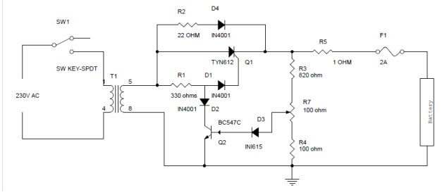
This is just simple circuit for a battery charger which uses SCR.
After I finished my circuit, it was working perfectly but then I noticed that I was receiving only 6v at the output instead of the required 12v. When I referred some places I was told that it was due to the SCR effect. Could anyone explain to me the correct explanation why I am getting this fault in the output. I would be grateful if anyone could help me with this.
This is my circuit diagram :-


A SCR only conducts in one direction - like a normal diode. So you are getting half the voltage of the secondary.
 

Insert a bridge rectifier between transformer and the rest of the circuit. Then your problem will be solved.
 

Attachments

  • charge.jpg
    charge.jpg
    15.4 KB · Views: 69

'SCR effect' - what is that supposed to be?

If you are measuring the voltage at the output with a DVM and the battery disconnected, the reading SHOULD be lower. The circuit produces unfiltered half cycles not DC so the reading will be at least 30% lower than the secondary voltage. The peak voltage can be the same though. If it isn't, the problem is probably lack of secondary voltage and a different transformer is needed. R2 and D4 alone will trickle charge the battery up to the full voltage the transformer is capable of, even if the SCR part of the circuit is completely removed.

I think adding a bridge rectifier will simply drop the voltage by another 0.7V or so.

Brian.
 

As there is no reservoir capacitor the out put voltage is a series of pulses, at the moment, the pulses are half sinewaves with alternate ones missing. If you try to measure this voltage your meter will read very low. If you use the bridge rectifier, then the situation improves as you will have a continous train of half sine wave pules, which will be a good improvement. There will always be an inbuilt problem because there will be no charging current until the pulse voltage exceeds the battery voltage, then the charging current will occur, until the level of the pulse drops below the battery voltage. So the current might only flow for 10% of the time, so putting in a current meter, its reading will be the mean of the current pulses, while the peak current would be 10 times higher.
Also because you have only a half wave rectifier, the mains transformer can only deliver a half (or less) of its rated output.
Frank
 

Status
Not open for further replies.

Similar threads

Part and Inventory Search

Welcome to EDABoard.com

Sponsor

Back
Top