Continue to Site

Welcome to EDAboard.com

Welcome to our site! EDAboard.com is an international Electronics Discussion Forum focused on EDA software, circuits, schematics, books, theory, papers, asic, pld, 8051, DSP, Network, RF, Analog Design, PCB, Service Manuals... and a whole lot more! To participate you need to register. Registration is free. Click here to register now.

Odd fan PWM issue with PIC

Status
Not open for further replies.

markdem

Member level 3
Joined
May 16, 2006
Messages
58
Helped
0
Reputation
0
Reaction score
0
Trophy points
1,286
Activity points
1,830
Hi All,

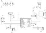
I have a odd issues driving some fans using PWM from my PIC.

Fan details are : 12v 200mA 2 wire. PWM frequency 20khz.

If I connect 1 fan to the circuit everything works fine. Problem is I need 2 fans to be driven.
When I connect the second fan (Same type, manufacture etc) I get the following results;

At 12v and 100% duty fans work fine.
At 12v and any other duty (except 0%) the PICs oscillator will stop.
At voltages <10v the fans will work fine except for duties between 88% and 92%. If I select these duties the PWM output will go to 0v after about 1 second. The PIC keeps working as I can send it commands.

I can connect 1 larger fan (600mA) and it will work fine so I am guessing it is not a current issue.
I have also tried a different pair of fans (from a different manufacture) and get the same results.
I don't have a pair of 3 wire fans so I can test that.

Anyone have any ideas what could be doing this, or what else I can test\try?

Thanks
 

Attachments

  • FAN.png
    FAN.png
    8.7 KB · Views: 50

Although the malfunctioning at the narrow range of the duty-cycle would not make much sense, you probably should connect a ceramic capacitor in parallel with the fan just for avoid generation of spikes at the fan coil that has a strong inductance characteristic.
 

It is also possible if these are the kinds of fans used to cool microprocessors that they are already using internal oscillators and your external signal is 'strobing' with them. Do you have capacitors (>10uF) across the fan wires? If not, try adding one and see if it makes a difference.

Brian.
 

Do you have capacitors (>10uF) across the fan wires? If not, try adding one and see if it makes a difference.

The problem may be of the opposite kind. Recent fans have already large input ceramic capacitors for EMC purposes. Connecting them to a pwm circuit creates large pulse currents which can cause supply voltage dips or ground voltage drops in an inappropriate layout (e.g. breadboard) that disturb the microcontroller.

In case, a capacitor should be connected between Q1 emitter and fan connector pin 2. Personally, I prefer a series inductor for the fan, turning the pwm circuit into a complete buck converter.
 

I was thinking that another option to avoid the spike problem would be the insertion of a small capacitor at the base side of transistor so that could form an RC network with a time constant near to switching frequency, therefore performing the control of the fan not at pulsed way, but biasing transistor with a continuous and variable current depending on duty-cycle.

However should be not easy to determine a linear region of the transistor without a previous simulation or polarization calculus. Another possible drawback of such an approach is the fact that depending on the transistor characteristics ( namely, the intrinsic range of current gain defined by manufacturer ), a small adjust on RC network certainly would be required.
 

Long wires can compound EMI issues interfering with the PIC. Keep them as twisted pairs to the fan. Add ferrite beads if necessary.

Keep in mind the Fans are BLDC with commutation that also may alias with PWM if not filtered properly inside fans.

Also the Darlington drops 1.3V. Use a FET with RdsOn <1 OHm.
 

Thanks for the suggestions guys.

I tried different capacitors across the fans, but it normally make the situation worse.
The wires from the fan are only about 50mm at the moment. I will try to twist them..
I normally would of used a FET in this case but I did not have one on hand.

I think I might give up on this one and use some 4 wire fans. There must be some kind of "cross talk" between the two fans that make them stop. Would be nice to know what, but life is too short :)

Thanks
 

Don't think it's crosstalk. Just increasing the peak current when connecting a second fan, the same thing what you did when adding parallel capacitors.

I keep my opinion that it won't happen with good layout and suffcient bypassing. I also support andre_teprom's second suggestion to slow down switching, although it increases switching losses a bit.
 

I've seen all kinds of wonky effects when I was experimenting with two fans in series using PWM. It forced me to use linear temperature control of the voltage. A slower PWM rate will help. THe thrid wire I guess is the Tach signal?

THe linear approach was cheap, stable and accurate for regulating speed vs temp over a 10deg range starting at 45 deg, and good for 1000 racks a month. The only problem I encountered was dead spots in the fans. SO I designed a simple start stop 3 second cycle for the Fan supplier to screen their fans and we saw no more failures after that.. ( Hall sensor alignment, where 1 or more resting positions would not start without help.)
 

thrid wire I guess is the Tach signal?

Some fans has an output signal of the type open collector, which really can be used to take the rpm, or even in a simplest approach, just to know if the fan still runs, what is the most usefull usage in my opinion, due a thermometer on board would measure the gathered temperature generated by each device too late due to heat propagation latency.
 

Status
Not open for further replies.

Similar threads

Part and Inventory Search

Welcome to EDABoard.com

Sponsor

Back
Top