Continue to Site

Welcome to EDAboard.com

Welcome to our site! EDAboard.com is an international Electronics Discussion Forum focused on EDA software, circuits, schematics, books, theory, papers, asic, pld, 8051, DSP, Network, RF, Analog Design, PCB, Service Manuals... and a whole lot more! To participate you need to register. Registration is free. Click here to register now.

Two stage op amp used as a comparator; different results using process corners (TT...

Status
Not open for further replies.

shockingshockley

Member level 1
Joined
Dec 11, 2010
Messages
33
Helped
0
Reputation
0
Reaction score
1
Trophy points
1,286
Activity points
1,611
Hello

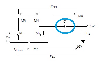
I am implementing my designed two-stage op amp (with a compensating capacitor Cc) as a comparator in my analog circuit.

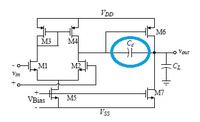
I run process corners TT, FF, and FS, and my output of the analog circuit is good and okay but not in SF and SS. When I remove the compensating capacitor, the output is now good in SF and SS while not in TT, FF, and FS.

Is there an explanation? Or do I need to redesign. Because the fault in the circuit is in that op amp. Thank you.
 

Hi

What do you mean by the output is good? What are you looking at? Are you running stb or ac simulations, to check stability of your 2 stage opamp?

This type of opa needs a compensation cap, so it is pretty sure that you would need to redesign.
 

You could try and find a smaller compensation cap which will do for all corners. Or you can try an RC series compensation.
 

Comparator works without negative feedback loop so it doesn't need a compensation. How do You simulating this comparator and what do You mean as "good result"?
 

You could try and find a smaller compensation cap which will do for all corners. Or you can try an RC series compensation.

I try lowering the 3pF capacitance value but to no avail. I don't have any background on RC series compensation.
Hi

What do you mean by the output is good? What are you looking at? Are you running stb or ac simulations, to check stability of your 2 stage opamp?

This type of opa needs a compensation cap, so it is pretty sure that you would need to redesign.

I am running transient simulations.

Comparator works without negative feedback loop so it doesn't need a compensation. How do You simulating this comparator and what do You mean as "good result"?

Well actually, I am trying to simulate in IC level these MPPT circuit of Lim:


When the power of the solar array at BLUE node is determined, the waveform in TT, FF, and FS looks like this:

Close to 25 Watts average.

But the wave form in SF and SS looks like this:


Like I said earlier, for the comparator, I used a two-stage op amp with a compensating capacitor. When the capacitor is removed, the output in FF and FS will be similar to SS and SF (previous wave form when the capacitor is still connected) and vice versa.
 

Hi

1. Which component on the last schematic are you designing? is it the op-amp withe the 51k at input?
2. the waveforms you are showing are voltages on which node? is this the blue node?
 

1. The comparators (after the differentiators) are the one. However I use two stage op amp as a comparator coz I believe it does not affect the functionality.

2. The waveforms are in terms of power of the solar array P(SOLARMODULE). P(SOLARMODULE) = product of voltage at BLUE node VPV and voltage at node of resistor Rs . I use the solar panel SPICE model from Castaner and Silvestre Book.

I can provide you with my hspice code if you need to see it. Thank you.
 

Hi again

In general there is no problem to use an op-amp as comparator, although it might be an over-design. so this is ok

The schematic you show for the op-amp used as comparator won't work. It has N-channel mos input, so it cannot operate with the positive input tied to ground.
You should use a Pmos opamp input.


Moreover, I don't understand your computation of P(Solarmodule). It can't be the product of 2 voltages.
 

Ok. Thanks for suggestion. I will redesign my op amp. Well actually instead of tying the other positive input to ground, a 0.6 volt is fed in that input. But well thanks anyway.

- - - Updated - - -

could you help me design a 5V pmos-input comparator? i am using tsmc 0.35. thanks
 

Hi

For example you could implement this basic comparator topology, using pmos input pair:
**broken link removed**

The amount of tail current flowing in your differential pair will determine the speed of the comparator

Cheers
 

Status
Not open for further replies.

Part and Inventory Search

Welcome to EDABoard.com

Sponsor

Back
Top