Continue to Site

Welcome to EDAboard.com

Welcome to our site! EDAboard.com is an international Electronics Discussion Forum focused on EDA software, circuits, schematics, books, theory, papers, asic, pld, 8051, DSP, Network, RF, Analog Design, PCB, Service Manuals... and a whole lot more! To participate you need to register. Registration is free. Click here to register now.

Amplifier isnt doint what it is supposd to do, in current sinking.

Status
Not open for further replies.

xReM1x

Member level 5
Joined
Mar 25, 2014
Messages
83
Helped
0
Reputation
0
Reaction score
0
Trophy points
6
Activity points
586
hi.
I "desigend" a linear adjustable current source from 3V voltage refrence and rail to rail amplifier. it works fine.. unless I go below ~7V and than the output current start dropping, and I'm trying to understand why does it happend, the amplifier is configured as an buffer but the output and the voltage on the inverting input is not the same.
here is the schematic :
16519b69ae1ab691b12e20ca2037d20d.png

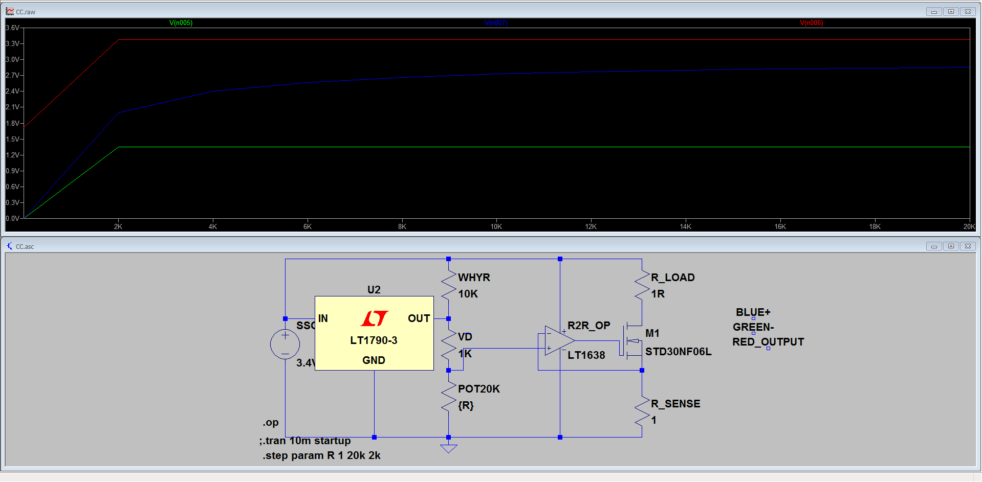
I'm pretty sure this schematic worked today without problems, just now this started to happend. anyone have any idea? or any suggestion to the schematic (VIN going to be 3.3V to 12V and current supposd to be adjustable from at least 10mA to at least 2.8A)
 

What's up with that resistor from the reference output to the input voltage? Why is that there? Also, not sure how you expect to get 2.8 Amps out of 3.3 volts with a 1 ohm load and 1 ohm reference resistor.
 

What's up with that resistor from the reference output to the input voltage? Why is that there? Also, not sure how you expect to get 2.8 Amps out of 3.3 volts with a 1 ohm load and 1 ohm reference resistor.

Ignore the resistor I always forget to remove than save the schematic so it is just sitting there.
also, what do you mean by "not sure how you expect to get 2.8 Amps out of 3.3 volts with a 1 ohm load and 1 ohm reference resistor."
in real life if I would a load (not resistive load) would this is not happend or what?
 

You SAID you want to get up to 2.8 amps, and that your input could be as low as 3.3V. That won't work. All you said was that it didn't work below 7 volts. You DIDN'T say what you were trying to get. Your graph is no help. If I had to guess, I'd say you were trying to get 2.8Amps out. That means you've got 2.8 volts across R_sense. The threshold voltage of that MOSFET is about 3 Volts, maybe even 4V, which means the gate voltage has to be at least 5.8 volts (but that would be at zero drain current, not 2.8A).

So basically, you probably don't have enough Vgs to get the MOSFET conducting when your supply drops. I'll bet it works fine with a lower current set point, right? You could verify this by looking at Vgs with a higher input voltage.
Yes, you were right it was the gate threshold voltage (Vgs). so I tought about putting this mosfet: "IRF3709PBF"
In the datasheet it says the Vgs is max 3V and min 1V, so I guess it is supposd to be fine, the only thing is that there is no such mosfet in LTSPICE so I cant confirm it, unless you know any logic level mosfet with low gate voltage that exist in ltspice, would you think IRF3709PBF would work? also, for current limiting for a power supply this schematic is good? (the input voltage as I said is going to be 3.3V min and max ~12V, adjustable from 5mA - 2.8A~
 

It's quite easy to determine the reason for "unexepected" (but actually expectable) output current in simulation by looking on MOSFET Vgs, Vds and Vd.

A circuit can be either designed for typical or worst case transistor parameters. In the former case expect about 2.5 V Vgs at intended output current, in the latter e.g. 3.5 V. It adds to Rref voltage drop. So a straightforward way to lower the minimal supply voltage would be reduce the reference (shunt) resistor value.
I'm sorry but I didnt understand what you said. what exacly do I have to do (in english that I can understand?)
edit: I just notcied it up, the mosfet I was using in the picture has typcial 1.5V Vgs. so, what is going on?
 
Last edited:

I say, use lower R_Sense value.
If I use 0.1Ohm resistor, when I apply 12V the current goes up to almost 11A. so, not exacly what I need.
 

If I use 0.1Ohm resistor, when I apply 12V the current goes up to almost 11A.
If you don't adjust the voltage divider accordingly.
 

If you don't adjust the voltage divider accordingly.
the voltage divider output ~2.8V.
is there any chance you can build this circuit yourself in ltspice and try something out? I'm still trying to understand what is the problem.
 

I'm under the impression that barry has explained the problem exhaustively in post #4.
 

You need to go back and learn how current sources work. If you have 2.8 volts across a 0.1 resistor, you're going to get 28 amps. Soooo, if you want less current, your voltage into the opamp should be...(the answer is left as an exercise for the student)
 

You need to go back and learn how current sources work. If you have 2.8 volts across a 0.1 resistor, you're going to get 28 amps. Soooo, if you want less current, your voltage into the opamp should be...(the answer is left as an exercise for the student)
thanks for your help mimimi, the answer is 0.3V. BUT!
thats only if my input voltage is exacly 12V. my input voltage is going to be variable (~3.3V to ~12V). so.. what do I do now?
also I indeed have no idea how current source work. that was right.
 

................ the answer is 0.3V. BUT!
thats only if my input voltage is exacly 12V. my input voltage is going to be variable (~3.3V to ~12V). so.. what do I do now?
also I indeed have no idea how current source work. that was right.
The voltage needed across R_SENSE for a given constant-current is independent of the supply voltage.

The circuit works by having the op amp adjust the gate voltage of the MOSFET with negative feedback from the voltage across R_SENSE so that the R_SENSE voltage equals the reference voltage from the pot.
The only time the power supply voltage affects that is when thsy voltage is too low to to provide the sum of the required voltages across the load and sense resistor or if there's not enough supply voltage to provide the required Vgs plus R_SENSE resistor voltage for the desired current.
 

A few comments:

You have the simulation right in front of you! Click the nodes and account for the voltages and currents!

The opamp is going to make the voltage at the + pin and the voltage at the - pin the same which means it's going to regulate the sense resistor so its voltage is equal to the + pin, and the + pin in this case is set by your voltage divider. Ohms law tells you exactly how much current this should equate too.

Current sources tend to confuse people for various reasons but one way to wrap your head around it is flip around how you think about a voltage source. A voltage source supplies current in order to regulate voltage. Voltage sources always have a limited amount of current and loads "use up" that current.

A current source supplies voltage in order to regulate current and always has a limited amount of voltage. When you try to run off 3.3V, you have a very small amount of voltage to work with. If your load is 1ohm it's going to use up 2.8V to get to 2.8A. Your problem was that your sense resistor was also 1ohm and needed 2.8V to get to 2.8A. So 3.3V just can't do the job. In this case you have a solution: reduce the voltage the sense resistor "uses up" at 2.8V, and adjust your reference voltage accordingly.
I got it now, it all works, the only thing I'm having problem now is how to limit the current without putting any load (and I cant use a dummy load with a switch because voltage) but I guess I could put the potentiometer on the lowest while the load is connected so yeah I will just buy the parts.
 

What do you mean 'limit current'? A current source is by definition going to supply a given current.
 

What do you mean 'limit current'? A current source is by definition going to supply a given current.
without any load connected I cant limit the current that going to a load without putting first the load, lets say I have a load that draws 5V 2A I first need to connect it them set the current that I want using the potentiometer, but without any load how can I see the current im limiting?
 

Either you calibrate your pot, or the voltage coming off it, or you use a switch and fixed load (which you say you can't do). I don't understand why you can't use a fixed load; voltage has nothing to do with it.
 

Status
Not open for further replies.

Similar threads

Part and Inventory Search

Welcome to EDABoard.com

Sponsor

Back
Top