Continue to Site

Welcome to EDAboard.com

Welcome to our site! EDAboard.com is an international Electronics Discussion Forum focused on EDA software, circuits, schematics, books, theory, papers, asic, pld, 8051, DSP, Network, RF, Analog Design, PCB, Service Manuals... and a whole lot more! To participate you need to register. Registration is free. Click here to register now.

Effect of impedance mismatch on ac response

Status
Not open for further replies.

iVenky

Advanced Member level 2
Joined
Jul 11, 2011
Messages
584
Helped
37
Reputation
76
Reaction score
35
Trophy points
1,318
Location
College Station, Texas
Activity points
6,124
Hi,

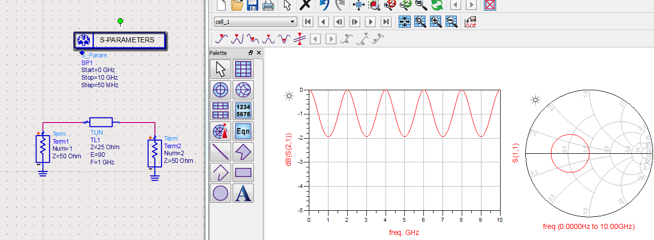
I have a question. Why is the insertion loss (or cable loss) plot of a channel across frequencies not smooth (as shown below) when there is impedance mismatch? It has several ups and downs across frequencies that I am not able to understand. Could you please explain me in detail?
Figure_07.gif
Thanks
 

if you have a signal source , a piece of cable and a terminating impedance and you measure the power in it. You only get a truly "flat" response when the terminating impedance is the same as the Zo of the cable. If the cable has a high loss then you get Fig. 2, as the frequency increases, the losses increase, so less power is seen. If the terminating impedance is not exactly the Zo of the cable you get reflections on the cable which reflect back and are absorbed by the generator. But the power that is reflected back show up as a loss on the through power.
Frank
I understand that but why is it kind of ups and downs ? It's kind of periodic with frequency. That's what I don't understand.
 

I understand that but why is it kind of ups and downs ? It's kind of periodic with frequency. That's what I don't understand.

If the frequency response of a mismatched cable is rippled (ups and downs), it indicates-
-either a reactive load on cable end, or,
-a damaged or wrongly made cable with mechanical impedance irregularities.

Actually, when the satellite TV started in 1980s, the IF frequency band, 0.95 through 1.45 GHz, was considered easy to use existing UHF coaxial cables. Those cables were manufactured with impedance irregularities over length, so we observed "gaps" in frequency coverage, ups and downs that "eliminated" certain TV channels oer the IF bandwidth.
New IF cables are made with a constant characteristic impedance that does not vary over length, and most of such problems are gone.
 

If the frequency response of a mismatched cable is rippled (ups and downs), it indicates-
-either a reactive load on cable end, or,
-a damaged or wrongly made cable with mechanical impedance irregularities.

If the cable impedance is different from the source & load impedance, we also get that ripple. Looking at Smith chart, it's obvious that we have worst case reflection where cable length is 90/270° and no reflection where cable length is 0°/180°/360°. The dip in transmission is seen at cable length is 90/270° etc


To elaborate chuckey's comment.

The first picture seems to show a short piece of 75 ohm transmission line in a 50 ohm system. You get no reflections if the cable length is an even multiple of λ/4 and maximum reflection if it's an odd multiple. Very basic RF engineering.

P.S.: I see volker@muehlhaus already showed the same effect with 25 ohms cable.

We can see any mismatch on any transmission line as standing waves (also in free space). Such waves can be seen as a "ripple".
 

Status
Not open for further replies.

Part and Inventory Search

Welcome to EDABoard.com

Sponsor

Back
Top