Continue to Site

Welcome to EDAboard.com

Welcome to our site! EDAboard.com is an international Electronics Discussion Forum focused on EDA software, circuits, schematics, books, theory, papers, asic, pld, 8051, DSP, Network, RF, Analog Design, PCB, Service Manuals... and a whole lot more! To participate you need to register. Registration is free. Click here to register now.

How to extract results from.the graph obtained from sonnet

Status
Not open for further replies.

nesan

Member level 2
Joined
Jan 20, 2015
Messages
46
Helped
1
Reputation
2
Reaction score
1
Trophy points
8
Location
Tamil nadu,India
Activity points
275
The patch antenna for operating 2.4 ghz resulted graphs which I attached. can someone explain me what are the results I got like gain ,vswr,impedance,etc., output graph2.gifoutput graph1.gif
 
Last edited:

Sonnet gives Far Field parameters only, not gain.
If you know s-parameters, it means that you know the impedance,vswr etc.. what is the problem..??
 
  • Like
Reactions: nesan

    nesan

    Points: 2
    Helpful Answer Positive Rating
nesan, as explained earlier: Only the expensive version Sonnet Professional can calculate the antenna gain from current density. The free Sonnet Lite can not do this.

The other parameters that you asked about can be plotted directly from the viewer.

Thanks a lot for the information. is there any possibility or formula or calculation procedure to calculate gain manually using the values such as zin vswr s11 y11 z11 because am a student who is not economically strong to buy professional software
 

Ok, I can do that.

here is my project file sir please see this and correct it with your experience in this field to make my antenna to produce 2.4 ghz results and post the results with gain and gerber file which i required for display in pcb as an antenna Thanks in advance and thanks for your time sir .View attachment 2.4 exact.rar
 

here is my project file sir please see this and correct it with your experience in this field to make my antenna to produce 2.4 ghz results and post the results with gain and gerber file which i required for display in pcb as an antenna
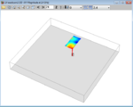
No, I will not do all the work for you. As I told you, this is your student project and you need to learn by doing this yourself. I gave you tutorial links and antenna design is also described in the Sonnet manuals. Now it is your job to read this and create your design. Many students have done that before.

I calculated at the antenna gain for your antenna and it looks really bad. Then I looked closer at the antenna and it makes no sense. Your antenna is completely messed up. You have created a lossy capacitor to the absorbing top cover. Why is the air layer thickness above the patch 6.122e-5 mm instead of half wavelength?

And why is the feed at the edge, instead of centered? You have seen patch antenna shapes before in the tutorials, why do you ignore all that? Why do you waste the time of people who were willing to help you?
currents.PNG2.4_rect_gaintotal.gif
 
Last edited:
  • Like
Reactions: nesan

    nesan

    Points: 2
    Helpful Answer Positive Rating
No, I will not do all the work for you. As I told you, this is your student project and you need to learn by doing this yourself. I gave you tutorial links and antenna design is also described in the Sonnet manuals. Now it is your job to read this and create your design. Many students have done that before.

I calculated at the antenna gain for your antenna and it looks really bad. Then I looked closer at the antenna and it makes no sense. Your antenna is completely messed up. You have created a lossy capacitor to the absorbing top cover. Why is the air layer thickness above the patch 6.122e-5 mm instead of half wavelength?

And why is the feed at the edge, instead of centered? You have seen patch antenna shapes before in the tutorials, why do you ignore all that? Why do you waste the time of people who were willing to help you?
View attachment 114329View attachment 114328

Oh am so sorry for mistakes and I just got some results only when feeded at the edge. and may I know the corrective measures to make a better antenna
 

hi edabord from the great help I designed and simulated patch antenna thanks now am triyng same in ie3d it doesnt produce results so please suggest me step by step tutorial in ie3d to design 2.4 ghz rectangular patch antenna
 

Status
Not open for further replies.

Part and Inventory Search

Welcome to EDABoard.com

Sponsor

Back
Top