Continue to Site

Welcome to EDAboard.com

Welcome to our site! EDAboard.com is an international Electronics Discussion Forum focused on EDA software, circuits, schematics, books, theory, papers, asic, pld, 8051, DSP, Network, RF, Analog Design, PCB, Service Manuals... and a whole lot more! To participate you need to register. Registration is free. Click here to register now.

[AVR] Help Me with 8X8 matrix C Program

Status
Not open for further replies.

codename25

Member level 3
Joined
Jan 15, 2015
Messages
65
Helped
0
Reputation
0
Reaction score
0
Trophy points
6
Activity points
555
Hi,
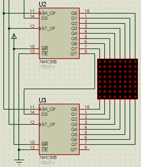
I have a schematic for an 8X8 Led Matrix using At mega 16 and 74HC595 shift registers. But i'm stuck with the code because i don't know C program much. I'm searching for a code similar to mine so i can edit that. Please Help me out of this. Thanks in Advance.


What is happening when you run the code on the controller?
What error(s)/problem(s) are you getting?
Please explain.
 

Hello. I program Microchip and Freescale MCUs only, I tried to start with AVR but where I live programmers and good MCUs are expensive.

I made a C function to drive exactly the same IC, I used it to control a 16x2 LCD when I ran out of pins. Make sure it can supply every LED row current. By the way, you must add resistors to rows OR columns. I think you didn't put them because proteus works well without them.

I joined both latches clock so you may have to modify the code a bit to send a separate clock. You will need 3 pin, 1 data and 2 clocks.

Since you use 2 registers, you should use 1 data, and 3 clock (1 for data and 2 for each output latch). Take into account that you can share both data clock signals if you don't send the output latch update clock to the register you don't want to change/update.

Here goes the code:

Code:
void Reg_des (unsigned char bin)	//FUNCION ANDA!!!!
{
	unsigned char cnclk;
								
	for(cnclk=0;cnclk<9;cnclk++)		//Counter --> "9" is the number of cycles
	{
		RDDT=(bin>>cnclk) & 1;			//RDDT is a pre-defined pin!! This line moves the 8-bit entered 
                                                                   //value one more time per cycle and gets the last bit
		Delay(500);                     //Delay, it's made with another function
		RDCLK=~RDCLK;					//Sends clock to RDCLK --> PRE-defined pin.
		RDCLK=~RDCLK;
		Delay(500);					//Generated by function, don't have to use.
	}
	Delay(500);
}

You can supress both delays, it all depends how fast your MCU is running and how the signal will get to the IC pin (noide, inductance, capacitance, etc). It seems that a 500ns works well (running at 8MHz divided by 4).

As you can see the process is made 9 times instead of 8, it's because as both clocks were joined, another 9th was needed to update the output latch with the 8th bit sent.

If you use a separate clock you must change the value from 9 to 8.

If you have any doubt, don't doubt in asking me. Hope you find it useful.
 
Thanks for the reply Udayan92. I haven't started coding yet. I have a code which worked without any shift registers (Rows and columns connected directly to the MUC). I want to edit that code and make compatible for shift registers. My real problem is, I don't know how to send the binary data (Ob00000001) serially bit by bit to the shift register data pin. Can you please explain how to do it. I'm attaching my code below.Thank you.

Code:
#define F_CPU 20000000UL
#include<avr/io.h>
#include<util/delay.h>
unsigned char seq[]={

0b11100001,
0b11111010,
0b11111010,
0b11111010,
0b11100001,

0b11111111,
0b11111111,

0b11100000,
0b11111011,
0b11110101,
0b11101110,
0b11111111,


};
int main()
{
DDRA=0xFF;

DDRB=0xFF;
PORTA=0;
PORTB=0;
int i,j,k;
while(1)
{
for( k=0;k<12;k++)
{
for( j=0;j<10;j++)
{
for(i=0;i<12;i++)
{
PORTA=(1<<i);
PORTB=~seq[i+k];
_delay_ms(0.03);
}}
}}

return 0;
}
 

[Moved]Help me Shifting data in 74HC595

Thanks for the reply BrunoARG. Sorry, I'm very basic in Programming. I assume the code you gave me is for sending data serially bit by bit to the Shift registers. If so, how to send a binary data bit by bit to the shift register. I'm posting my code which worked without any shift registers. Thank you in Advance.

Code:
#define F_CPU 20000000UL
#include<avr/io.h>
#include<util/delay.h>
unsigned char seq[]={

0b11100001,
0b11111010,
0b11111010,
0b11111010,
0b11100001,

0b11111111,
0b11111111,

0b11100000,
0b11111011,
0b11110101,
0b11101110,
0b11111111,


};
int main()
{
DDRA=0xFF;

DDRB=0xFF;
PORTA=0;
PORTB=0;
int i,j,k;
while(1)
{
for( k=0;k<12;k++)
{
for( j=0;j<10;j++)
{
for(i=0;i<12;i++)
{
PORTA=(1<<i);
PORTB=~seq[i+k];
_delay_ms(0.03);
}}
}}

return 0;
}
 
Last edited:

Shiftout() must be a function which uses 2 predefined pins since it's the easiest method to shift. As you use registers with output latch then you should use another to activate/refresh it or join both clocks, but the function must be configured for 8 clocks instead of the 9 needed.

To send values you call a function and send a 8 bit number to it, for example ShiftOut(0b01101101); or call the function with its name (which I told you is called Red_Des() but you can change its name puting any other as Shift()).


Just copy the value table you put in order. If you have 10 combination then you should send 10 bytes or 10 times 8 bits. Take into account that you'll need a delay between byte sending because you won't be able to see any image in the matrix if it changes so fastly as shift registers can do.
 
Status
Not open for further replies.

Similar threads

Part and Inventory Search

Welcome to EDABoard.com

Sponsor

Back
Top