Welcome to our site! EDAboard.com is an international Electronics Discussion Forum focused on EDA software, circuits, schematics, books, theory, papers, asic, pld, 8051, DSP, Network, RF, Analog Design, PCB, Service Manuals... and a whole lot more! To participate you need to register. Registration is free. Click here to register now.
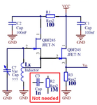
Can i design oscillator in this picture with using bc547, if yes, how i can do. .by the way in multism the oscillator in picture doesnt have output frequency in Mhz range.but cource lecturer did it!.
A transistor needs base bias voltage and current for it to begin to turn on and amplify. A Jfet is already turned on and amplifies when it does not have any input bias voltage.
There are hundreds of schematics about your Hartley Oscillator in Google Images, some of them work.
Some of them show the transistor with no input bias so it will not work unless it is kick-started. Here is one showing the wrong symbol:
FET threshold voltages are different than BJT ones and the first don't have almost gate current when BJTs work with a base current. The circuit will need modifications.
You can use any good CMOS logic inverter with good decoupling. ω=(LC)e-½ where C is the series equivalent of C1, C2 and allow for stray and input capacitance of a few pF. Try here
Tuneable coil, varicap network or trimmer cap as your choice for tuning.
This site uses cookies to help personalise content, tailor your experience and to keep you logged in if you register.
By continuing to use this site, you are consenting to our use of cookies.