Continue to Site

Welcome to EDAboard.com

Welcome to our site! EDAboard.com is an international Electronics Discussion Forum focused on EDA software, circuits, schematics, books, theory, papers, asic, pld, 8051, DSP, Network, RF, Analog Design, PCB, Service Manuals... and a whole lot more! To participate you need to register. Registration is free. Click here to register now.

[SOLVED] simulation errors with atmega16

Status
Not open for further replies.

dhk

Newbie level 5
Joined
Oct 12, 2014
Messages
9
Helped
0
Reputation
0
Reaction score
0
Trophy points
1
Activity points
56
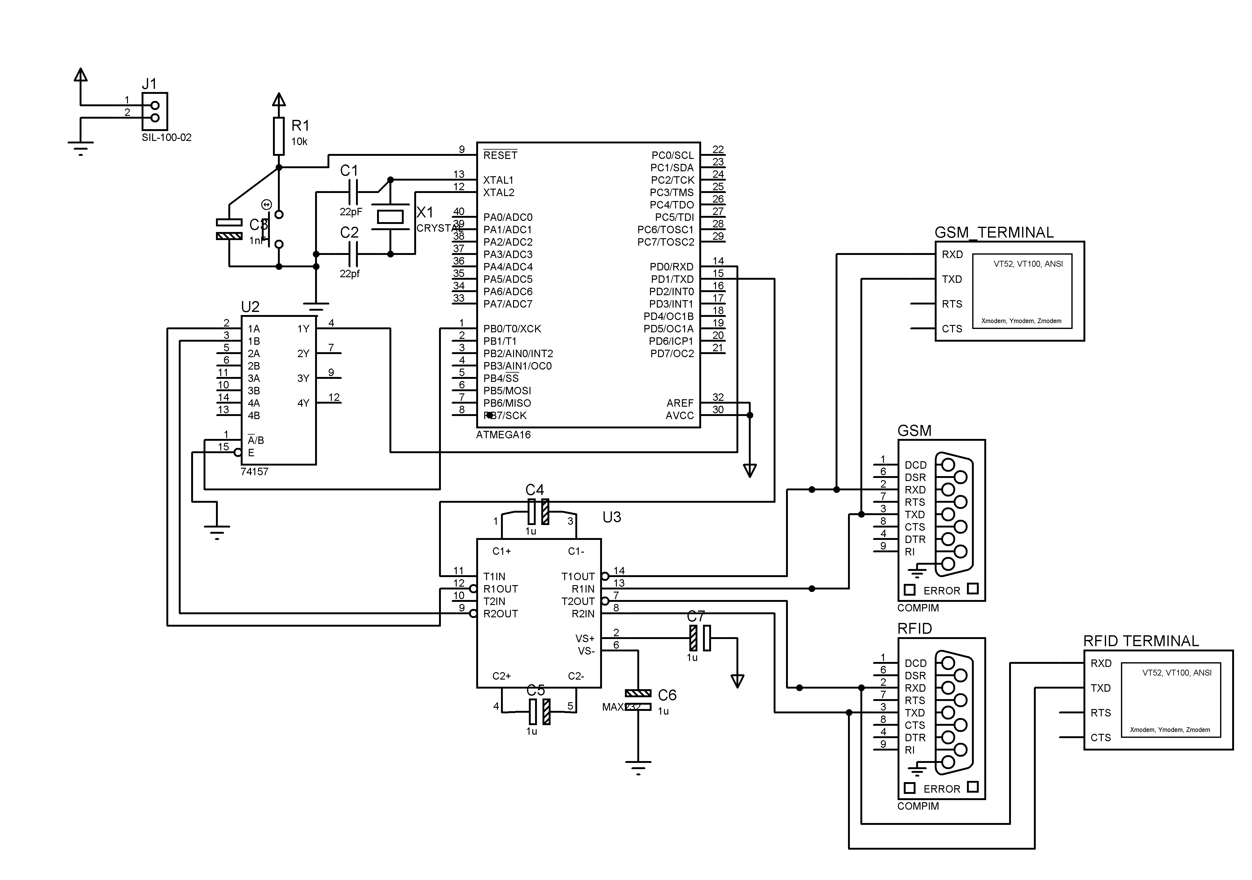
I have made the following circuit where I have interface RFID and GSM with atmega16 using a MUX.
During simulation, I am getting "Logic contention detected " at T1out and T2out. I am unable to understand the error here.
can someone explain the error.


Attachments

  • Development board.BMP
    1.4 MB · Views: 48

It happens if pins are configured as inputs and used for outputs. Configure UART Tx as output pin and Rx as input pin using DDRx register.
Zip and post complete project files.
 
  • Like
Reactions: dhk

    dhk

    Points: 2
    Helpful Answer Positive Rating
Thanks for the reply.
I tried making the Tx and Rx as output and input pins, but still the same error appears.
Below is the complete project files.
 

Attachments

  • Atmega16.rar
    36.9 KB · Views: 47
Last edited by a moderator:

Remove MAX232 from Proteus Schematic. You don't need it in Proteus. Connect COMPIM pins directly to AVRs UART pins through your MUX. In your code there is no code related to baudrate setting.

Also in the USART ISR Compiler shows variable value in blue. It seems it is a reserved keywork. So, change the variable value's name to some other thing.
 

The baud rate is mentioned in the UBRR.
Is there anything that has to be programmed besides this?

- - - Updated - - -

I removed the Max232. Now the same error appears at the Tx pin on MCU and Rx of GSM.
 

Remove VT if COMPIM is used. Try attached project. Load my Proteus file and type in GSM VT (Virtual Terminal). It will Echo in ECHO VT. You had set DDRB to 0x00 and so PORTB was all input. PORTB.0 had to be output type to select MUX channel. Load proper .hex file from project debug folder.
 

Attachments

  • Atmega16.rar
    104 KB · Views: 49

Hi,

It is a simple and common problem, If two outputs of diff logics are short circuited it will show "Logic contention detected ".

That means one output is giving high and another output is low.

In your diagram you wrongly connected the DB9 connector pins T1 out to RXD instead of TXD, a output from DB9 connector.

Just correct it, thats all.
 

What are you trying to do ? Do you want to control some device using GSM if RFID tag matches with TAG stored in MCU ? If yes then you don't need MUX. You connect RFID out to AVR UART RxD and GSM UART Rx to AVR UART TxD. This way when a RDIF TAG match occurs then AVR sends out SMS thtough GSM. If you want to read SMS using AVR then you need MUX or bi-lateral switch.
 

Status
Not open for further replies.

Similar threads

Part and Inventory Search

Welcome to EDABoard.com

Sponsor

Back
Top