Continue to Site

Welcome to EDAboard.com

Welcome to our site! EDAboard.com is an international Electronics Discussion Forum focused on EDA software, circuits, schematics, books, theory, papers, asic, pld, 8051, DSP, Network, RF, Analog Design, PCB, Service Manuals... and a whole lot more! To participate you need to register. Registration is free. Click here to register now.

Can I use a photo transistor to turn on a BJT cleanly?

Status
Not open for further replies.

supak111

Newbie level 4
Joined
Oct 14, 2014
Messages
5
Helped
0
Reputation
0
Reaction score
0
Trophy points
1
Activity points
58
Hey guys I'm trying to turn on a BJT cleanly and fully in my light activated circuit. I use an LDR right now so the turn on time for my BJT is slow and I'm not even sure it it ever turns the BJT fully. I was wondering if I replace the LDR with a photo transistor would that have a better turn ON/OFF time?

My circuit is being activated from a very powerful 1/2watt LED light pointing right at the now LDR, there is almost no external light present and the 1/2 watt LED turns digitally so its a clean ON.

If a phototransistor wouldn't help, is there any other way to improve the circuit easily/cheaply to achieve a fast clean ON?

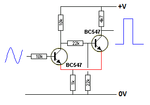
Here is my circuit right now:

ldr.gif
 

Aside from the fact that the current directions are all wrong on your diagram, it's impossible to determine what's going on with your circuit. As a rule of thumb, you need to drive the base with about ten times your collector current to ensure the BJT is saturated. A photo transistor would probably be faster.
 

Thats just the circuit I used, I didn't actually make the picture shows above.

Ok so since my BJT will only be conducting 30ma C to E, are you saying I need 300ma on the base to fully switch ON my BJT?

One other question I had, If I replace the LDR with a photo transistor or by a photodiode (not sure which would be better), when the light form my LED hits whichever one, do they have a clean ON or are they just like the LDR and slowly start flowing current?
 

Actually by understanding this circuit the LED will latch in ON condition once the LDR caught some light, after that LED will make its own light and will keep itself ON through LDR.

Ok so since my BJT will only be conducting 30ma C to E, are you saying I need 300ma on the base to fully switch ON my BJT?
No 3mA

One other question I had, If I replace the LDR with a photo transistor or by a photodiode (not sure which would be better), when the light form my LED hits whichever one, do they have a clean ON or are they just like the LDR and slowly start flowing current?
they are comparatively faster than LDR, but you cant just modify the circuit for that, can we know How much reaction time you need to switch on the circuit ?
 

In my device LDR is in a box with a tiny hole on the box. The 1/2watt LED that my LDR gets light from is placed right over the tiny hole so no there light can reach the LDR other then from the 1/2watt LED. The LED in my circuit is away from the LDR so that LEDs light can't hit the LDR.

And I'm sorry but I'm not sure how much faster my circuit needs to be. I know that I just need to hopefully make this circuit act like a digital circuit and not analog which is whats happening now using an LDR. Someone in another forum told me to use a schmitt trigger on the base and that would make my circuit much fast but that kinda complicates my simple circuit. So I was thinking maybe first try just replacing the LDR with a photo diode which I read are fast and that might give me a fast enough ON on my BJT.

I also though about replacing my BJT to a mosfet since I keep reading they are faster and much more suitable as switches?
 

LDR = slow, but still has a resistance when fully illuminated.
Phototransistor = faster but you need to limit the current into the second transistor or it may pass enough to damage it.
PIN Photdiode = fastest but produces a small voltage so you need to amplify it before it can be used to drive a transistor to saturation.

You really have to quantify the speed you need before going further. The different technologies have vastly different response speeds, an LDR response could be a slow as several seconds whereas a PIN photodiode can be as fast as 0.000000001 seconds!

The choice of transistor is only relevant if you are switching high voltage or current, from your description so far, it would make no difference which you used.

Brian.
 

About 47 years ago I made a Schmitt Trigger circuit with two transistors and also an IC was available. They switched VERY fast.
You can make a Schmitt trigger circuit like this one with your photo transistor as the left transistor:
 

Attachments

  • discrete Shmitt Trigger.png
    discrete Shmitt Trigger.png
    4.2 KB · Views: 147

Thats Ausioguru, I think I'll try your circuit as it seems simple enough.

Hey guys what kind of current can a photo transistors usually pass when they are fully on? Is it something tiny like 3ma or something more useful like 30ma?
 

Thats Ausioguru, I think I'll try your circuit as it seems simple enough.

Hey guys what kind of current can a photo transistors usually pass when they are fully on? Is it something tiny like 3ma or something more useful like 30ma?

Advantage of using schmitt trigger is you will get exact square wave.

But, I will just put the photo transistor directly inplace of LDR with resistor series in transitor base. according to the dark current of photo transistor in the schematic in #1.
 

I haven't purchased any photoT's yet but after looking into a few and looking at the datasheet its seem that most photo transistors conduct 20-30ma max. Since my whole circuit needs to conducting 30ma, could I actually remove everything (resistors, BJT and LDR) in my circuit and replace it all with just 2 photoT in parallel?

2 parallel photo transistors will see ZERO light all the time until my 1/2watt LED turns ON and since even 1/2watt LED turn ON very fast my photo transistors should respond just as fast back so my circuit should turn on fast too... Is that how this would work?
 

Transistors and photo-transistors are not made exactly the same. Even with the same part number some are more sensitive than others unless you are lucky to find two the same. When two are in parallel then the more sensitive one will conduct most or all of the current and quickly burn out due to the overload. Then the weaker one will be overloaded and it will also quickly burn out.

Series emitter resistors can be added to make a better match between two photo-transistors.
 

Hi, Can we know what is your exact application, because you just making light coupling with LED and LDR and lighting another LED with it.

It was just like a optocoupler with some big box. why do you need two light sensors and two LEDs. we can give you some more input.
 

As indicated by AudioGuru you need high gain with positive feedback to make a clean, noise free transition to turn ON/off

The thresholds of ON\OFF is determined by % of positive feedback which is also called hysteresis.

Std CMOS schmitt triggers have large hysteresis of 50% with a large tolerance, so you may prefer to amplify a low threshold with gain and dial your own resistor ratio for hysteresis and mean threshold or use a simple 0.7v threshold in NPN to drive Schmitt Trigger or use any Op Amp,or Comparator with + feedback ratio of output swing referred back to (+)input. Then the mean threshold is determined by (-) input side.


Here are some examples https://www.google.ca/search?q=schm...a=X&ei=pqI-VP_eBY-2yATEq4GgAg&ved=0CAgQ_AUoAQ
 

Hi Audioguru,

You are even more puzzling. unknown your circuit !!!

Might be i could understand in the morning..
 

His cct is called a bootstrap design which raises input impedance with common emitter feedback using CB mode for feedback so you have 2 stage gain with raised input impedance for sources like LDR.

Low impedance emitter 2nd stage feedsback to low impedance emitteras input to pickup emitter current and reduce base current like picking up boot with strings and foot..
Primitive but effective.

http://www.talkingelectronics.com/p...ansistorAmplifier-P2.html#THE SCHMITT TRIGGER
 

Hi SunnySkyguy,

I am asked about the OPs application. He is doing some light coupling, then why shdnt he use a optocoupler.

That is my question.
 

The problem with LDRs is they are lambertian response or wide angle and lack optics.

photo diodes from Panasonic on the other hand are fast log sensitivity over 4 decades and have optics for narrow beam 30 deg. You can also use a 10 deg LEd in reverse bias to amplify current and drive a CMOS inverter with negative feedback 1M:10M for an analog gain of 10 or 100k:10M for 100 gain on any buffered inverting gate, then drive a schmitt trigger gate.

Low power, high gain fast , directional and hysteresis dependant on signal level & noise. Very reliable with decoupling caps.
 

Status
Not open for further replies.

Part and Inventory Search

Welcome to EDABoard.com

Sponsor

Back
Top