Continue to Site

Welcome to EDAboard.com

Welcome to our site! EDAboard.com is an international Electronics Discussion Forum focused on EDA software, circuits, schematics, books, theory, papers, asic, pld, 8051, DSP, Network, RF, Analog Design, PCB, Service Manuals... and a whole lot more! To participate you need to register. Registration is free. Click here to register now.

[SOLVED] I can't simulate driving TMR1 with a crystal using MPLAB SIM - PIC 16F684

Status
Not open for further replies.

ljcox

Full Member level 5
Joined
Feb 1, 2006
Messages
252
Helped
25
Reputation
50
Reaction score
23
Trophy points
1,298
Location
Melbourne Australia
Activity points
3,110
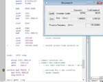
I have MPLAB V8.73 and I'm using MPLAB SIM to simulate a programme I wrote for a PIC 16F684.

I want to drive TMR1 with a 32.768 kHz crystal.

But when I try to simulate this situation, TMR1 does not change.

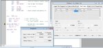
I set _INTOSC_OSC_NOCLKOUT in the configuration and the following bits in the programme:-

PIE1, TMR1IE

INTCON, PEIE

T1CON, TMR1CS; T1CON, T1OSCEN & T1CON, TMR1ON

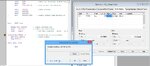
I'm using PIR1, TMR1IF to determine when an overflow of TMR1 occurs.

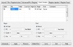
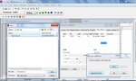
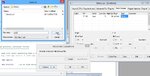
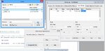
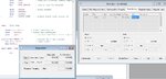
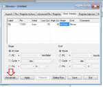
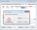
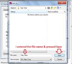
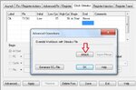
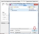
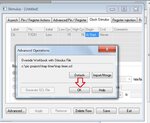
I setup the Clock Stimulus as shown in the attachment.

What am I missing?

Any advice will be appreciated.

Len
 

Attachments

  • Clock stimulus.jpg
    Clock stimulus.jpg
    102.7 KB · Views: 104

Thanks for the response.

I don't reload TRM1.

I want a delay of approximately 1 hour so I simply let it cycle and count the overflows.

Len
 

I did not include an ISR because I don't need one.

If you look at my programme, you will see that I poll the TMR1 overflow.

It works very well if I drive TMR1 from the internal clock. My problem is that I can't simulate the 32.768 kHz crystal - as I said in my first post.

Thanks for the links & your continuing interest.

Len

Hi,

I tested the same out on a 18f4520 Sim with the same results, no clock Stimulus worked be it RCO, T1CLK or T1OSC1 or T13 etc etc.

Followed MPlabs User Guide on Sim , see page 235, with no success.

Like you could only get it to work if I used the internal oscillator as input by changing T1CON bit 1 to 0.

I've used T1 and a 32k crystal with assembly on many chips for many years and they do work well, so nothing wrong with the actual circuit and hardware running.

A couple alternative way you could test your code -

In your code set T1CON to run from the internal osc and in Sim Stopwatch and your code set the processor internal frequency to 125K so the Fosc/4 will give 32k..ish to Timer1 and a near 1 second output from Tmr1.

The other way , if you have a Microchip programmer Pk2/3 or ICD is to run your code on the actual hardware using breakpoints etc to control the flow and examine your registers.

- - - Updated - - -

Hi,

Managed to get it working, seems if you follow this method it does work ok.

Close Mplab, go into your project folder and delete any existing stimulus .sbs or .scl files.

Restart your project and enter your Clock Stimulus values, do not apply or save but press Advanced.
Click the Generate SCL box and Save the file, then click the Attach file followed by OK to return to your main screen , (but leave the Stimulus window open) , and Run your code as shown.

To change any of those Settings, stop Sim and click Advanced on the Stimulus box and then Detach the file which then allows you to enter new values into clock box.
Then repeat the above sequence to generate, save and attach your scl again.
 

Attachments

  • 000149.jpg
    000149.jpg
    47 KB · Views: 105
  • 000153.jpg
    000153.jpg
    91 KB · Views: 102
  • 000152.jpg
    000152.jpg
    83.3 KB · Views: 120
Thanks for the suggestion. I tried it but it did not work.

However, I did not get exactly the same sequence of windows as you did. See the attachment

So I expect you have a later version of MPLAB. Which version do you have? I have 8.73.
 

Attachments

  • Stimulus 5.jpg
    Stimulus 5.jpg
    376.9 KB · Views: 93

Hi,

I'm on the last version, V8.92 though not sure if there is much difference with V8.73 in respect of the Stimulus.

Not sure what you have pressed to get that window, but not sure why it cannot continue to work ?

Just gone back to it again , this time with an existing .scl file and it works fine.

If you have done the sequence correctly to should notice how the Clock windows data entry area darkens slightly just after you press the Attach icon.
 

Attachments

  • 000154.jpg
    000154.jpg
    82.6 KB · Views: 101
  • 000155.jpg
    000155.jpg
    87.9 KB · Views: 84
  • 000156.jpg
    000156.jpg
    83.5 KB · Views: 85

Hi,

Looked a few microchip files, seems your 8.73 is very close to 8.92 and cannot see any mention of changes to the Stimulus routines.

Attached is a video showing how I have created and use the Clock Stimulus

Not used a screen recorder before so please let me know if it plays back ok.
 

Attachments

  • test.rar
    1.8 MB · Views: 82

Thanks very much for your continuing assistance and the video.

I was able to run the video successfully, how did you do it?

I could not make it work with my version of MPLAB.
So I installed v8.92 and tried again.

However, it still will not simulate the crystal oscillator.

I have inserted the screens of the procedure I followed below.

As far as I can see, I am following the same procedure as shown in your video.

So I'm wondering if there is something wrong with my Initilisation sub routine.
See the second last screen.
I showed the bits I set in my post #1.
 

Attachments

  • Screen 1.jpg
    Screen 1.jpg
    111.1 KB · Views: 84
  • Screen 2.jpg
    Screen 2.jpg
    111.3 KB · Views: 95
  • Screen 3.jpg
    Screen 3.jpg
    103.6 KB · Views: 95
  • Screen 4.jpg
    Screen 4.jpg
    105.7 KB · Views: 93
  • Screen 5.jpg
    Screen 5.jpg
    107.8 KB · Views: 83
  • Screen 6.jpg
    Screen 6.jpg
    118.7 KB · Views: 89
  • Screen 7.jpg
    Screen 7.jpg
    132.4 KB · Views: 93
  • Screen 8.jpg
    Screen 8.jpg
    213.2 KB · Views: 93
Last edited:

Hi,

That screen recorder is the first free one I tried, its just a simple start and stop, perfect for me :grin:
For the codec I selected Microsoft Video 1, though have since been told some others will make the recording space less.
https://www.sketchman-studio.com/rylstim-screen-recorder/

Rather than me trying to fault your code, might be easier for you to try running mine and see if it works for you.
As you can see it was part of a ISR but now just made to run direct.
 

Attachments

  • ljcox.zip
    1.9 KB · Views: 73
  • Like
Reactions: ljcox

    ljcox

    Points: 2
    Helpful Answer Positive Rating
I simulated your programme, used your Clock Stimulus procedure & it worked successively.

Thus there may be an issue with my initialisation code.

So I'll programme a PIC & test it on my PIC tester & see if it works.

Thanks for your help. I'll let you know the result.

Len
 

I simulated your programme, used your Clock Stimulus procedure & it worked successively.

Thus there may be an issue with my initialisation code.

So I'll programme a PIC & test it on my PIC tester & see if it works.

Thanks for your help. I'll let you know the result.

Len


Hi,

Glad it worked for you, does sound like a code or project setting thats not right.

If still stuck, if you want to post or PM your code, full or part, I will give it a try ..
 

Hi,

Found your original code in an earlier entry.

Found a fair few problems with the code, a real problem was the first build of your file, which said Build Successful, but if you expand to the full screen message it has several RAM errors - see jpeg.

If you see the returned code and look at the opening section / defines and the initialise routine you will see all my comments and correction and also the root cause of the Stimulus non functioning .

It works the Timer1/stimulus correctly now, see jpeg; however all your actual detailed code I have no idea if that works ok, looks quiet complicated .. will leave you to check that out.

Will pm my address for a few crates of XXXX :lol:
 

Attachments

  • TRAPok.zip
    211.2 KB · Views: 72
  • Like
Reactions: ljcox

    ljcox

    Points: 2
    Helpful Answer Positive Rating
Thanks very much for that.

I saw the RAM errors but could not see how to fix them. I have written many PIC programmes & have never seen that before.

I was able to simulate the code with the Fosc driving TMR1.
So everything worked correctly except when I tried to simulate the crystal oscillator.

I'll study your corrections later & report. I have another urgent job to do at the moment.

Thanks again, Len
 

PS - just realised, your post is headed Pic 684 and your code has an opening comment line saying 684 but your include directive states 648A ?

I have built the code as a 648A chip - no idea which is correct - though think the chip differences are small.
 
  • Like
Reactions: ljcox

    ljcox

    Points: 2
    Helpful Answer Positive Rating
Thanks again for your continuing interest.
Yes, I realised earlier (due to your comment about the 684 not having a PORTC) that I had transposed the 4 and 8.

And that is the reason why I had to specify the various registers - INTCON, etc. I had never had to do that before & could not understand why it was necessary in this case.

I looked at the p16F648.inc file & all of the regs were there. But I was calling up the p16F684.inc file.

I'm sorry about the confusion. I'll return to the project tomorrow & see if I can make it work.

Len
 

Status
Not open for further replies.

Similar threads

Part and Inventory Search

Welcome to EDABoard.com

Sponsor

Back
Top