Continue to Site

Welcome to EDAboard.com

Welcome to our site! EDAboard.com is an international Electronics Discussion Forum focused on EDA software, circuits, schematics, books, theory, papers, asic, pld, 8051, DSP, Network, RF, Analog Design, PCB, Service Manuals... and a whole lot more! To participate you need to register. Registration is free. Click here to register now.

Wireless control for DC light dimmer circuit without using a microcontroller

Status
Not open for further replies.

Madhura Bhashitha

Newbie level 4
Joined
Oct 10, 2014
Messages
5
Helped
0
Reputation
0
Reaction score
0
Trophy points
1
Activity points
43
Hey !!
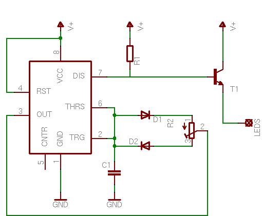
I was thinking of making a wireless light dimmer for Dc bulb without using a micro controller when i searched in internet i was able to find many circuits of light dimmer (wireless) with using micro controllers. how can you make a light dimmer without using a micro controller ?? if you can give me some schematics it will be great. thanks .
 

Light dimmers generally DON'T use microprocessors-they use an RC and a triac.

But if you need to add wireless to it, you might want to look at using an radio-control (different RC) chip set.
 

IR sensor output is digital, for this you will need flip flops, Timing circuits using 555, up down counter, DAC, Transistor, UJT triggering circuit, It is not impossible but comparatively difficult.

Are you still want to do without controller ?
 

yep i need to try a one without using a micro controller can you help me with the design with circuit diagram or explain how it should work. sorry for the trouble i'm bit new to electronics.
 

There's lots of ways of doing this. You could just use an IR LED/Detector to transmit a PWM signal. That signal at the receiving end would drive a MOSFET. Use a 555 at the transmitter to control the pulse width.
 
Yeah i can help you in how you can do this, but not with the complete schematic, is it ok for you?

There are lot of ways are doing this, but to have a dimming up down control, you will need at least the circuits i said in #3. You have to understand all of them.
 
thanks guys , i learned bit about PWM dimmer circuit using a 555 timer , in that simple circuit gives me the ability to dim the bulb using variable voltage input i have to replace that voltage input by a IR sensor right ? IR sensor will give me an out put as PWM i have to give that output to THRS and TRG right ? can i give it directly or do i have to go through a MOSFET . And why do i need to use a MOSFET there ? here the circuit i'm referring to. by the way thanks alot for replying.

8788509900_1413126383.png
 

I would put the 555 on the transmitter side. Then the receiver would just use the pulsed input signal to turn a MOSFET on and off. But I think I already said this.

I don't know WHAT all that talk about flip-flops, DACs and UJTs is all about.

- - - Updated - - -

Wait. I retract what I just said. My method will only work if you are constantly sending a pulse train. That's just stupid. My apologies. Now I realize you might need some flip-flops, etc. after all.

So I'm going to jump to the 'why NOT a controller' group? A PIC or similar would be a really inexpensive way to do this.
 

Are you serious ? you want to control brightness of LED ? Then all you need is,
Untitled.jpg


But actually you cant use the circuit in #7, The PWM dutycycle can be only varied by the pot. and the control input is only to change the frequency.

All you needed to do is a auto resettable integrator (Its a analog circuit which will do all the 555 timer, operations of counter and dac)

You can use your TV remote for brightness control (obviously the brightness will also control when you using it for television)
 
Last edited:

If you want to alter the light output via a remote control, then there are at least two methods, one is when you press the button the light gets brighter over 5 seconds then dims over 5 seconds to OFF. So taking your finger of the button the light will stay at the selected value. The other way would be to have a + and a - button to increase/decrease the brightness.
In any case you need some sort of "memory" in the receiver to hold the selected value of light output or you have to continuously transmit pulses, which will wear the battery out in the transmitter.
The easiest way is to generate pulses say, 1 every .5 seconds at the transmitter. At the receiver these pulses are routed to a counter with as many bits you can get in one package. So as you hold the button down, the counter goes, 00001, 00010, 00011,00100 etc. From each output of the counter you wire a resistor to the input of an op amp with each resistor being twice the value of the previous one. With this arrangement the voltage at the output of the op amp will have 32 different values, so these voltage levels will step through, the suprise will come when the counter reaches 11111 (max brilliance), it will then go to 00000 (light off) and start again. If the pulses stop the counter will stay at the same value. There I have invented a third way of doing it!! :)
Frank
 

Thanks for the help guys . we designed the circuit and worked properly with using rf transmitter and HT12e/Ht12D encoder decoder pair. here's the schematic of our circuit the dimmer part.Untaaaaaitled.png
 

What if AC (mains) frequency varies ? Light brightness vary due to change in firing angle ? A 8 pin microcontroller can control in a better way.
 

Thanks for the help guys . We designed the circuit and it worked properly.
Whenever I hear the word "we" then the thread is usually from a student asking for somebody to do his homework for him. But why doesn't your teacher teach YOU how to design it?
 

I think in their mind they are thinking that they push us to think in our own way and learn more from self learning.
and @milan the main purpose not to use a micro -controller. with a micro-controller its much more easier.
 

I think in their mind they are thinking that they push us to think in our own way and learn more from self learning.
Woudn't it be in this way that they want you to stuggle a lot for doing all things for marks and in turn they may learn from it that how you did it.
 

Status
Not open for further replies.

Part and Inventory Search

Welcome to EDABoard.com

Sponsor

Back
Top