Continue to Site

Welcome to EDAboard.com

Welcome to our site! EDAboard.com is an international Electronics Discussion Forum focused on EDA software, circuits, schematics, books, theory, papers, asic, pld, 8051, DSP, Network, RF, Analog Design, PCB, Service Manuals... and a whole lot more! To participate you need to register. Registration is free. Click here to register now.

Mass production of inverter

Status
Not open for further replies.

mrinalmani

Advanced Member level 1
Joined
Oct 7, 2011
Messages
463
Helped
60
Reputation
121
Reaction score
58
Trophy points
1,318
Location
Delhi, India
Activity points
5,285
I have a few questions about mass production of inverters. (house-hold inverters, 12V/230V, 600VA to 2.5kVA)

1. What is the typical profit margin on an inverter... any rough idea?
2. Why are HF inverters not as common in the market as the bulky LF version? High price? Lower reliability? Or is it that computer chips and other power electronic components were not "so-cheap" 10 to 15 years ago?

Someone with any sort of experience in inverter/power electric company, please share your experience.
 

1. Varies too largely depending on scale of manufacture and specific design down to the component. The choice of a specific microcontroller over another would bump up the cost as would the choice of driver circuitry, etc. Profit margins also tend to increase with increasing power and for sine wave inverters.

2. Circuit is simpler for bulky LF version. Parts are readily available. Parts (except the transformer itself) are cheaper. Less hassle since practically everyone around you can make the bulky LF transformer. Also, the bulky LF transformer is much more durable and very difficult to destroy upon regular use. That said, the HF inverters can be made for about the same price if not cheaper. Except that most companies don't feel the need to go through a redesign since it probably won't be worth it.

Hope this helps.
Tahmid.
 
Thanks for the reply!
But it's still not completely clear...

The components of HF inverters may surely be expensive, but I suspect the LF transformer alone to contribute more than 50% of the price.
An 800VA transformer weighs around 8Kgs and I think it should cost nothing less than Rs. 1000 ie. 18$ to build one (in India). What makes HF inverters so expensive that they make-up for this extra 18$!?
Also, would an 800VA HF inverter not be as small as a wi-fi router? Would space reduction not be worth?

The cost is usually the parts themselves. For example, two high-low side MOSFET gate drivers along with two stages of MOSFETs (instead of the one stage for LF), two ferrite core transformers plus another battery charging stage, etc. There are ways to reduce this. For example, using discrete transistor-based drivers instead of the high-low side driver chips would be a common one.

I don't think it would be that small (as a wifi router). Think about it. You have so many MOSFETs and two transformers additional to all control circuitry.

I am curious though, have you completed the design for this inverter? How did you minimize the cost in the circuit?

Don't get me wrong. I'm all for HF inverter design. In fact, the reason we stopped using the HF inverter over the LF inverter is cost itself - it ended up being more expensive. However, things might be different in Delhi - so pricing is something you should reevaluate. Pricing varies too much depending on location - for example, I would think that an 800VA LF transformer in New York would probably cost quite a bit more than $18 (my hunch - haven't actually gone looking for one).
 

1. My anticipated price is approximately Rs. 1600 i.e. 26$ @ 100 units for an 800VA inverter. (Most parts are imported from the US)
2. Gate drivers are indeed made of discrete component, costing approx 0.25$ for low side and 0.35$ for high side
3. The second stage is not MOSFET based. I use NXP thyristors costing 0.4$ each.
4. Why two transformers? I have come across a few other texts suggesting the use of two transformers. Unfortunately, they just suggest. Till date I have not been able to find a valid explanation for this. Please can you explain or suggest appropriate texts/links. Any help regarding the two-transformer concept will be extremely valuable.
5. Another cost as well as size reduction results from using a central heat-sink linked to heat centers through carefully sized heat conductors.

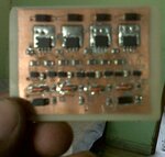
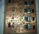
M attaching a photo of the first stage of the inverter (Without heat sinks), this will give a rough idea of the size, ie. 4cmx4cm The circuit is hand-made (print and then etch manually). The size will reduce further when manufactured by a CAM system.
 

Attachments

  • Capture01.JPG
    Capture01.JPG
    142.7 KB · Views: 107
  • Capture02.jpg
    Capture02.jpg
    190.6 KB · Views: 100

3. Did you use thyristors for the high voltage DC to 50Hz AC conversion? Did you use forced commutation?

2. Is your primary side full-bridge based? I was thinking about the gate drivers for MOSFETs in the second stage (high voltage AC to low voltage DC). Are you talking about gate drivers for the thyristors or the primary side MOSFETs?

4. Perhaps I was a bit unclear on this. I meant one transformer for the low voltage DC to high voltage AC conversion, and another for battery charging. Of course, they're both ferrite core transformers in this case.

That's a really good price and size for the design. If you can produce the finalized design within that price, you should definitely go for it.

By the way, where's the transformer(s)? Is the control circuitry on the other side? Did you measure the efficiency - are you using just one set of MOSFETs? Does this not have battery charging?
 

1. First stage is a MOSFET based full bridge, with discrete component driver. (Shown in the picture are 4 MOSFETs with 100A capability)
2. Yes the 50Hz h-bridge is thyristor based. It certainly uses forced commutation, but in a different way. I use low voltage, low cost, trench type MOSFETs in series with the thyristors for commutation. This reduces cost as well as enhances commutation speed. During the entire cycle it is ensured that the MOSFETs are not subjected to over-voltage (typically 40V).
3. As far as for the transformer, only one transformer may be used for both inverter/charger. The charger must be cut-out carefully when the inverter is active.
4. This is only the first stage. No components behind the board. I am assembling each module on a separate PCB for better troubleshooting. When the modules will have been tested individually, I'll put them all together.
5. Theoretical efficiency is between 89% to 92%. I still havent gone far enough to assemble the entire system, so actual figures are awaited.

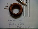
Now transformer needs a re-design. I need the leakage to be less than 250nH. With the current design m getting 900nH. Oil-cooling undoubtedly appears to me as a more economic option.
M attaching the photo of the x-mer

- - - Updated - - -

Was leakage not a major problem in your design?
 

Attachments

  • IMG00058-20140508-1146.jpg
    IMG00058-20140508-1146.jpg
    456.6 KB · Views: 94

In Indian power conditions, especially in rural areas power fluctuations are very high.
Even effect of lightning is very high so however reliable the design is break downs are quiet common so serviceability has to be there for any design to be successful in the market.
As per my experience HF inverters are having more failures and since SMD components are used component level service becomes a highly complex and skilled work and needs experts to do it.
If we want to change the entire board then since failures are frequent it does not justify the cost.

The margins in inverters vary from 15% to 40% for the manufacturers.
 
Thanks for the reply Mr. Mahasvar!
15% sounds like a small margin, I was expecting over 70%!
From your experience it seems that faliures are frequent and service will be a mojor issue. In that case a few test points on the PCB along with a computer aided troubleshooting system in the service center should be worth the cost?
 

That could solve the problem to some extend but a major market share lies with local people in rural areas who will not understand your computer aided troubleshooting system.
If you are planing to address a market like how big term people like Sukam, microtek, luminous etc. are doing then you might succeed.
one more issue in the service is that in transformer based ups even if a big lightening hits at least the transformer remains healthy which is almost 40% of the total system cost. Where as in HF models the total board will need to be replaced which is almost 90% of the cost.
 
There... I see your point!
I think the best I can do is to ensure easy troubleshooting of faulty components right from the design process itself. Perhaps by following a modular approach. Instead of a single large PCB, maybe we can have three of four smaller ones...
 

1. First stage is a MOSFET based full bridge, with discrete component driver. (Shown in the picture are 4 MOSFETs with 100A capability)
2. Yes the 50Hz h-bridge is thyristor based. It certainly uses forced commutation, but in a different way. I use low voltage, low cost, trench type MOSFETs in series with the thyristors for commutation. This reduces cost as well as enhances commutation speed. During the entire cycle it is ensured that the MOSFETs are not subjected to over-voltage (typically 40V).

How are you driving the thyristors?

5. Theoretical efficiency is between 89% to 92%. I still havent gone far enough to assemble the entire system, so actual figures are awaited.

How did you deduce this? What factors did you consider?

M attaching the photo of the x-mer
Are you sure that those wires are sufficient? 12V 600W means you'll be handling quite a bit more than 50A (especially when battery voltage dips under load). Additionally, which MOSFETs are you using? Are you sure that using one of each is sufficient?

Was leakage not a major problem in your design?

It was not, actually.
 

1. Firstly, the input to the thyristor bridge is a half sine wave (or |sin|), and not simply raw PWM. A low voltage series MOSFET is used in series with each thyristor for commutation.
2. Efficiency has been projected on the basis of worst-case power loss at each stage.
3. No, the transformer will surely not sustain a current as high as 70A in air. But a quick solution of the thermal equations with appropriate value of Raleigh's, Prandtl, and Reynolds number shows that it is possible, if dipped inside certain commonly available liquid hydrocarbons. With thicker wires, even transformer oil may help.
4. I wonder why leakage was not a problem. At 100khz, even a 500nH leakage, when referred to the secondary should translate to a reactance of approx. 300 ohm (which is several times larger than the load resistance!)

3. By dipping in a "cooling liquid" you take care of heat but that doesn't ignore the fact that the heat is produced, that power is dissipated. Have you worked out how much power you lose in that case? Why not go for a larger core and thicker wire as traditionally done?

4. Leakage wasn't an issue here. It was a big pain in the flyback battery charger (which is why that was discarded in favor of full-bridge).
 

The real thermal problem is dissipation of heat out of the core, owing to its small surface area and poor convective coefficient of air. Once the heat enters a liquid, although it is still present, but it is much easier to cool the liquid, than the core. It is possible to link the liquid tank to the central heat sink. However, to dissipate about 20W under natural convection would require a significantly larger core (and thus cost and space). It appears that the cost of core and copper will by far out-weight the cost of coolant and casing.
 

The real thermal problem is dissipation of heat out of the core, owing to its small surface area and poor convective coefficient of air. Once the heat enters a liquid, although it is still present, but it is much easier to cool the liquid, than the core. It is possible to link the liquid tank to the central heat sink. However, to dissipate about 20W under natural convection would require a significantly larger core (and thus cost and space). It appears that the cost of core and copper will by far out-weight the cost of coolant and casing.

Well, that's good for you then. That does lead me to wonder why this isn't done more in commercial inverters. What are the drawbacks you weighed out? What about safety issues with the cooling oil? By the way, which type of "oil" are you using?
 

Dear Mrinal,

Is your design is Voltage source or current source?
I wish you successful design.
 

Google recently announced compact Inverter design challenge called, THE LITTLE BOX CHALLENGE.
An open competition to build a (much) smaller power inverter, with a $1,000,000 prize.
link **broken link removed**

J.T.Rao
 
Status
Not open for further replies.

Part and Inventory Search

Welcome to EDABoard.com

Sponsor

Back
Top