Continue to Site

Welcome to EDAboard.com

Welcome to our site! EDAboard.com is an international Electronics Discussion Forum focused on EDA software, circuits, schematics, books, theory, papers, asic, pld, 8051, DSP, Network, RF, Analog Design, PCB, Service Manuals... and a whole lot more! To participate you need to register. Registration is free. Click here to register now.

Help with ultra wideband oscillator circuit

Status
Not open for further replies.

neazoi

Advanced Member level 6
Joined
Jan 5, 2008
Messages
4,118
Helped
13
Reputation
26
Reaction score
15
Trophy points
1,318
Location
Greece
Activity points
36,907
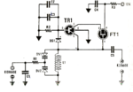
Hello, I have found this ultra wideband oscillator circuit in an old Greek magazine. It claims to operate from 0.5-450MHz and it never stops oscillating as long as it is powered by 3-15v vcc. The only component to be changed is the band-switching coil L1.

I would like to know how this circuit works if anyone has any clue.

There is some kind of feedback that allows the fet to regulate power to the transistor but I cannot find out how does it work.
Also DC should flow through L1 to GND which does not make sense for me.
 

Attachments

  • t.png
    t.png
    93.1 KB · Views: 690
Last edited:

It's a Lambda diode "negative resistance oscillator". Basically the combined FET and bipolar characteristics cause a dip in current as the voltage increases, make it appear to work like a resistor with a negative value. A very similar effect happens in Tunnel diodes.

There is a good reference to it here: **broken link removed**

Brian.

Great!
Thanks Brian. The range of this oscillator is huge. only the coil (and possibly the varicap for VHF/UHF) needs to be changed. I am curious to see how this would work (if it works) on audio as well. Also how undistorted waveform will be produced.

Do both transistors need to have high Ft for UHF or just the BJT?
Also would that potentially work with a BFRxxx transistor or uhf germanium transistors as well?
 

I would guess both transistors must have high Ft as they need to react at signal frequency. I'm without any lab at the moment while my house is being demolished and rebuilt (or will be as soon as the company building the foundations turns up! - very frustrating!) so I am unable to do any testing. I think the transition frequency 'Ft' and maximum operating frequency may be a little different in this configuration but I'm not sure which is higher. I think BFRxxx transistors should work fine. I've got lots of BFP640 here which have an Ft of 40GHz, they should do!

One of my "when I have the time" projects is to build a receiver using a similar circuit to the one in the web link but control the regeneration using a voltage from a microcontroller. I want to see if it is possible to automatically find the "sweet spot" just before oscillation starts so a highly selective receiver can be built with just a tuning control.

Interestingly, while emptying the house I came across some cassette recordings of US local radio stations in New York and Boston which I received on MW in the UK using a single transistor regenerative receiver. They were made in 1975/76 ! I doubt with the high levels of interference and many more low power stations in Europe there are today that it is still possible but it shows what can be achieved.

Brian.
 
  • Like
Reactions: neazoi

    neazoi

    Points: 2
    Helpful Answer Positive Rating
I would guess both transistors must have high Ft as they need to react at signal frequency. I'm without any lab at the moment while my house is being demolished and rebuilt (or will be as soon as the company building the foundations turns up! - very frustrating!) so I am unable to do any testing. I think the transition frequency 'Ft' and maximum operating frequency may be a little different in this configuration but I'm not sure which is higher. I think BFRxxx transistors should work fine. I've got lots of BFP640 here which have an Ft of 40GHz, they should do!

One of my "when I have the time" projects is to build a receiver using a similar circuit to the one in the web link but control the regeneration using a voltage from a microcontroller. I want to see if it is possible to automatically find the "sweet spot" just before oscillation starts so a highly selective receiver can be built with just a tuning control.

Interestingly, while emptying the house I came across some cassette recordings of US local radio stations in New York and Boston which I received on MW in the UK using a single transistor regenerative receiver. They were made in 1975/76 ! I doubt with the high levels of interference and many more low power stations in Europe there are today that it is still possible but it shows what can be achieved.

Brian.

These bfp 640 are great and they cost 0.73 on ebay!
It would be interesting to see (in combination with a similar fet-which one??) if this configuration can go higher in microwaves as well!
Yes I remember, you told me about your house in another post, I hope you get where you want as quick as possible.
These receivers are much promising for their minimal design. They lack the selectivity (usb/lsb) of modern designs but they have only a few components! The finding of the sweet spot point using a micro would be something me and many others would be interested in. I think you have to somehow detect the oscillation, rectify it and decide if you want oscillation (SSB) or not (just before the point of oscillation for max sensitivity and selectivity)
 

For me the circuit was working fine up to 400MHz starting from few MHz. At that time I remember I used a PNP with ft about 800MHz and a JFET almost the same. Usually is hard to find high ft PNPs.
BFP640 is NPN and the circuit use PNP.
The oscillator is sensitive to the type of diode, which should be a fast Schottky diode, and also is sensitive to the bias point (R2 should be adjustable).
The circuit oscillates with very high LC ratios, but this happen to the expense of distorted waveform, and also the stability was not impressive because there is a strong coupling of the resonator to the active element.
 
  • Like
Reactions: neazoi

    neazoi

    Points: 2
    Helpful Answer Positive Rating
For me the circuit was working fine up to 400MHz starting from few MHz. At that time I remember I used a PNP with ft about 800MHz and a JFET almost the same. Usually is hard to find high ft PNPs.
BFP640 is NPN and the circuit use PNP.
The oscillator is sensitive to the type of diode, which should be a fast Schottky diode, and also is sensitive to the bias point (R2 should be adjustable).
The circuit oscillates with very high LC ratios, but this happen to the expense of distorted waveform, and also the stability was not impressive because there is a strong coupling of the resonator to the active element.

Thanks for the useful feedback, I will try these.
I have some AF379 germanium transistors (ft=1200MHz) do you think they should work on the circuit being germanium?
I bet the oscillator could not be so stable as a narrow one, but I hope suitable stability can be achieved so that it could be used as a very wideband signal generator.
Followed by a single transistor mixer, with the LO and IF signals being the same signal produced by the oscillator, a simple doubler could be made, extending even more the range of the oscillator.
Maybe this amplifier such as the one in the post #4 in this thread https://www.edaboard.com/threads/200286/ could be used as a buffer amplifier for this oscillator? I worry because this is 50R input, whereas the oscillator output is not.??
 

Germanium transistor AF379 should be fine, you can try it.
To get highest frequency, C2 and C3 should be only one capacitor with small value (<10pF). Value probably depends by the PNP transistor used.
 
  • Like
Reactions: neazoi

    neazoi

    Points: 2
    Helpful Answer Positive Rating
Germanium transistor AF379 should be fine, you can try it.
To get highest frequency, C2 and C3 should be only one capacitor with small value (<10pF). Value probably depends by the PNP transistor used.

I have tried it. You were right, the situation where the sinewave is clean is quire rare, most of the time the waveform is triangular like or else distorted. I have not managed to make this oscillator work at more than 60MHz eventhough I used uhf techniques.
To help others, I believe it is not worth the effort. My other oscillator **broken link removed** shows almost an undistorted waveform and high amplitude stability.
 

Should go more than 60MHz using a 50nH inductor (about 3 turns, 5mm, air core), small value capacitors, and a fast switching diode. I cannot estimate how behave a Germanium PNP in this type of oscillator.
The sine wave is distorted due to the switching diode, even you visualize the waveform across the LC resonator. This is unusual in other types of oscillators, where the waveform across the resonator (at least) is pure sinewave. You need a buffer (emitter follower) to check the output signal, to do not load further the LC resonator.
 
  • Like
Reactions: neazoi

    neazoi

    Points: 2
    Helpful Answer Positive Rating
Hm... I think I am going to try another topology. I find the attached one very promising
 

Attachments

  • 6275404f5-1.pdf
    15.7 KB · Views: 220

That's much better as a general purpose oscillator. Note that you can 'invert' the circuit and use a positive supply which is probably more practical.

Brian.
 

That's much better as a general purpose oscillator. Note that you can 'invert' the circuit and use a positive supply which is probably more practical.

Brian.

I have not a clue how can I do this.
Also I need to know (in this negative vcc version) if the fets sources are connected to the -vcc side or the drains? I guess it is the sources.
 

Nothing changes, just reverse the supply connections. So R1 goes to ground and the tuned circuit goes to the positive supply. The only drawback is the tuning capacitor now has supply on it so you can't ground it. Make sure you have good decoupling across the supply and it should work just the same.

Brian.
 
  • Like
Reactions: neazoi

    neazoi

    Points: 2
    Helpful Answer Positive Rating
Nothing changes, just reverse the supply connections. So R1 goes to ground and the tuned circuit goes to the positive supply. The only drawback is the tuning capacitor now has supply on it so you can't ground it. Make sure you have good decoupling across the supply and it should work just the same.

Brian.
I built it (the negative version). The output is distorted again, but I took the output from the output capacitor and the article states that the signal present accross the LC is sinusoidal and not at the output capacitor.
Any thoughts of how can I extract the output from the LC without loading it too much?
I was thinking of one turn around L, so if can be made inductive coupling, but i do not know about the loading effect.
 

For output measurements you can use a buffer emitter follower.
Another type of multi-octave oscillator is the source-coupled FET oscillator.
As the other oscillator, stability and phase noise are meaningless, but provides very wide frequency range for high LC ratios.

8386250200_1403437153.gif
 

For output measurements you can use a buffer emitter follower.
Another type of multi-octave oscillator is the source-coupled FET oscillator.
As the other oscillator, stability and phase noise are meaningless, but provides very wide frequency range for high LC ratios.

8386250200_1403437153.gif

I have tried your circuit in the past https://www.zl2pd.com/HFRFgen.html and the result is very distorted waveform as well.

I am not aware of other topologies for wideband oscillators but the best circuit I have tried so far is the one in post #9
As you say stability is not very good above 1MHz or so, but the waveform is a very clean sinewave and the amplitude is very consistent up to about 10MHz and then starts to lower it's level but not distorting the waveform up to about 40mhz. Lower undistorted limit is about 20-30KHz but I have tried it to 5KHz distorted.
I would be interested if you have in mind other topologies to try.
 

Neazoi, can you give us the parts values to the lambda oscillator that you gave in the first post? Thanks and Regards
 

Neazoi, can you give us the parts values to the lambda oscillator that you gave in the first post? Thanks and Regards

r1=56k
r2=10k
r3=100r
c1=1nf
c2=10nf
c3=33pf
c4=10nf
c5=47pf
ds1=hp2801-5082
tr1=bfr99
ft1=bf245
 

Status
Not open for further replies.

Part and Inventory Search

Welcome to EDABoard.com

Sponsor

Back
Top