zereshki
Member level 1
Hello.
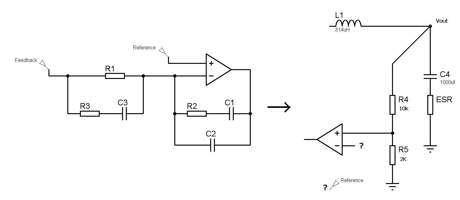
I designed a half bridge converter by using tl494 chip. and so it's 2pole - 2zero compensation network.
but this configuration is suitable for inverting error amp configuration not non inverting like tl494. Now I confused how to solve this problem for make circuit to be stable!
Actually using a RC feedback in non inverting configuration same as in ATX power supply(that use tl494 not SG series),just make one pole (at origin) and one zero.It make overall loop -2 slop at cross over frequency not -1. how it is possible to be stable? although there is not any instability in ATX !!!
circuit parameters:
Forward Gain included : [main voltage(for max line Ac=280v) & pwm control ramp=3.2v & transformer ratio=Ns/Np=11/34] =26db
L = 314 uH
C = 1000 uF (for esr:RC=1.6 us)
Osc freq = 55.5 KHz
Fcross = 5.5KHz
Vo=30v
Vref=5v
Regards