Continue to Site

Welcome to EDAboard.com

Welcome to our site! EDAboard.com is an international Electronics Discussion Forum focused on EDA software, circuits, schematics, books, theory, papers, asic, pld, 8051, DSP, Network, RF, Analog Design, PCB, Service Manuals... and a whole lot more! To participate you need to register. Registration is free. Click here to register now.

dual feeding in a single patch

Status
Not open for further replies.

sonia raj

Junior Member level 3
Joined
Apr 3, 2014
Messages
27
Helped
0
Reputation
0
Reaction score
0
Trophy points
1
Activity points
175
hello evryone..
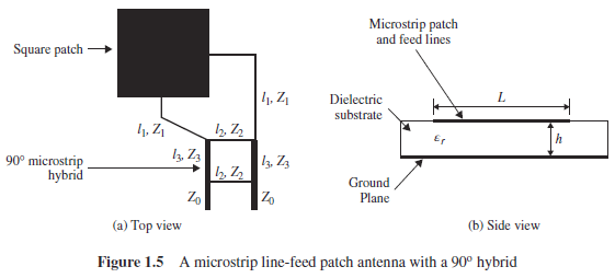
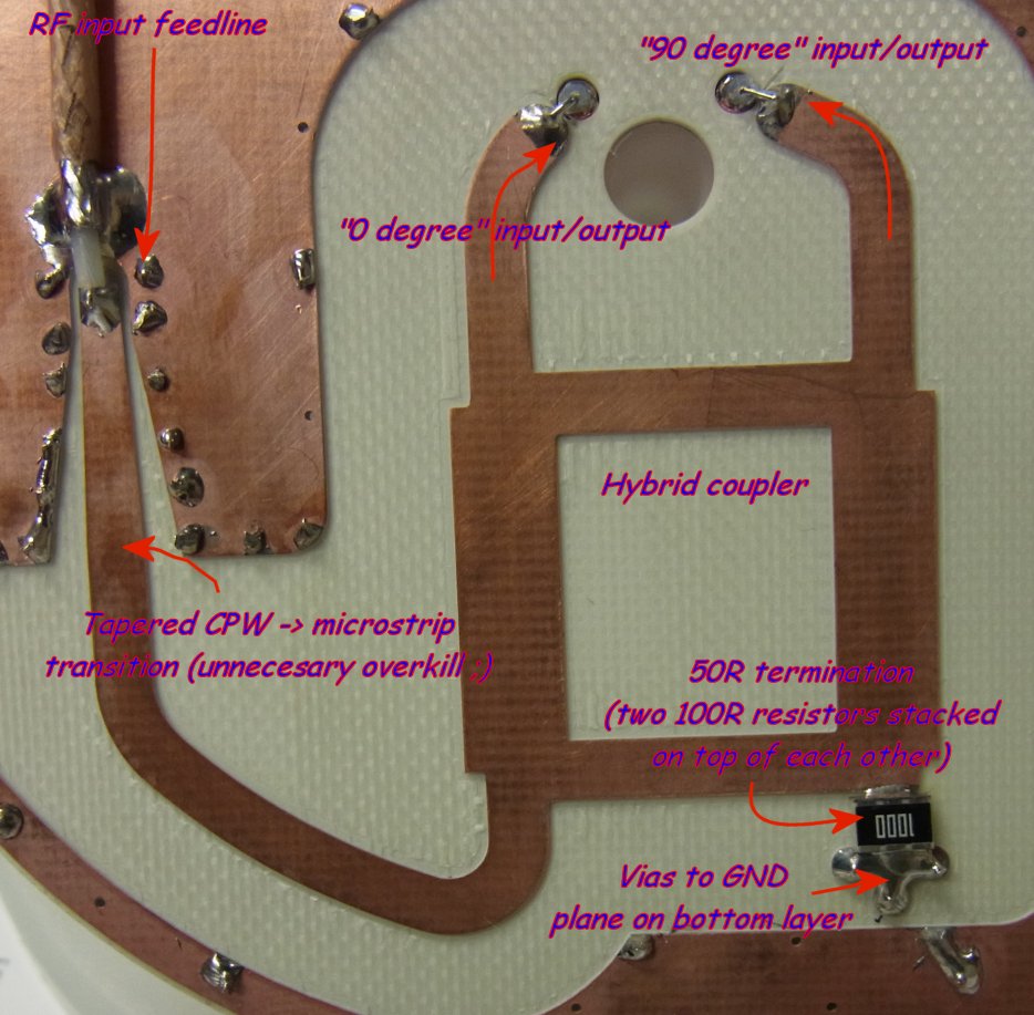
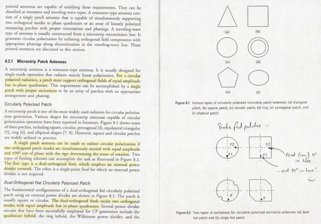
how to delay one feed among two feeds by 90 degree using a hybrid coupler..how to design hybrid coupler..m working in cst.please anyone help me i m working on a project on circular polarization:cry:
 

Pardon me for my ignorance but I am not completely sure what you are talking about. If you are talking about delaying a signal by 90 degrees, you should be able to do that with a phase shift filter or an inductor to have it lag based on what your frequency is. More details please.
 
Heya Sonia,

Microwaves101 has a brilliant description of hybrid couplers that work well for the generation of quadrature signals over a wideband for exciting circular polarisation.

I've made heavy use of the branchline coupler in the past (described at **broken link removed**) as a robust design that works over a wide frequency range and is relatively insensitive to variations in substrate and/or geometry (I cut my first few 2.4GHz attempts out of teflon PCB using a manual metalworking milling machine and they worked a treat!)

CST [the 2010 version] lets you calculate the appropriate geometry for the odd impedance transmission lines used within the coupler via a macro/utility located under Macros/Calculate/Calculate Analytical Line Impedance.

Cheers!

P.S. The nifty thing about branchline couplers is that you only have to exchange the connections to the feed & (terminated) isolation ports to reverse the phase lead/lag between the outputs and thus flip the circular polarisation :)
 
ya i have to make my antenna circularly polarized at 5.8 GHz. for this i m using dual feeding to excite patch.should i have to design phase shift filter or there is any option in cst studio to design it? i want to know how to delay feed..please help me..

- - - Updated - - -

hello thylacine1975
thanks
how to do it ?how to feed at two points in a single patch...
 

Hi Sonia,

You can do something like this, using the type of coupler proposed by thylacine1975:


Many variants are possible on the same principle: different feeding methods of the patch, replace the square shape by a disk.
It is possible to or use a Wilkinson splitter with a 1/4 wavelength delay in one of the branches instead of the 90 deg. coupler, but bandwidth is not so wide.
Regards

Z
 
I don't think CST has the ability to help specifically design the hybrid coupler - you'll have to manually lay down copper bricks in a square arrangement, using the geometries suggested by CSTs macro utility for each of the 2 x 90 degree Zo and Zo/sqrt(2) lines described on the microwaves101 site. There's nothing magical about using CST though - you could of course design the coupler network (which could be a Wilkinson etc as mentioned by zorro) in some other package (such as Agilent's ADS etc) and simply re-draw/import the design into CST for simulation.

While I've never driven a patch antenna in quadrature, I've previously constructed a similar network as to what you're contemplating for a 2.4 GHz circularly polarised quadrifilar helix antenna. Here's a picture of what the prototype network looked like:


Zorro's post shows one possible way of exciting the two orthogonal modes of a patch antenna - via two feedlines connected to the periphery of the patch. An alternative arrangement is the "probe feed", shown in Fig. 8.2 of the following scan from the "Microstrip Antenna Design Handbook" by Ramesh Garg et al.


(I've highlighted relevant bits of the text for you. The Fig. 8.3 referred to in the text is essentially the same picture as posted by zorro).

The approach (probe/edge fed) you select is largely a matter of personal choice, although probe feeding has issues with thick substrates due to the series inductance of the probe - go tinker and see what works for you!
 
thank you thylacine i understand this
I don't have to design it practially I only have to show it to my teacher that my antenna design which have simulated in cst is circularly polarised.
now another problem has generate that i rotate my square patch at 45 degree then i fed it with probe and when i m feeding another probe at 90 degree differene there is 4 boolean operations coming in between this while there is only two operations takes place(as given in cst microwave studio help tutorials)now what to do?
please help me..
I hope you understand
 

yes tony_lth
here is my design
6523725800_1396977296.png
 

But (if I'm not wrong) this shape produces circular polarization with a single feed. In fact, the figure shows only one feed.
Why do you ask "how to delay one feed among two feeds by 90 degree using a hybrid coupler" and said thet you are using double feed?

Z
 
zorrao,
ohh..i was trying but result was not coming thats why i have done stubbing in it by using single feed..okk now here is the design and in this i have to delay one feed by 90 degree..
1319293100_1396981765.png
 

An easy way to get a 90 deg shift is to make one line a quarter wavelength longer than the other. Why make things complicated? One answer is that you might want more bandwidth.

Azulykit
 
hello azulykit
which line do i feed it by quarter wave transformer actually i am using probe feeding
 

If your objective is circular polarization it, does not matter just make the two feeds different lengths. Reversing the length difference will reverse the polarization sense.
 
okk thanks everyone for helping me
now i have done direct feeding at two appropriate place.and my s11 is coming exact at desired frequency bt my question is do i cnsider s21,s12 and s22 also or not?
please suggest me...
thank you :)
 

okk thanks everyone for helping me
now i have done direct feeding at two appropriate place.and my s11 is coming exact at desired frequency bt my question is do i cnsider s21,s12 and s22 also or not?
please suggest me...
thank you :)


Yes.

s22 represents how well the other port is matched. I would expect to see a value that is similar to s11. s21 and s12 represent the coupling between the ports. Usually one would want to see low coupling (high isolation). -20 dB might be a useful target.

Azulykit
 

okk thanks azulykit
let me do then i will tell you.
 

hello azulykit
my s11 and s22 are similar.but what about s12 and s21..should they be same?
 

Yup - they should be the same if the geometries of the two orthogonal dimensions (excited by each of the probe feeds) of the patch are the same.
i.e. if it's a square patch and the feed points are at right angles to each other and offset from the centre by the same amount.
 
s11 and s22 should be the same if the conditions described by Thylacine are met. Ideally they should be 0.
s12 and s21 must be equal anyway becase the network is reciprocal. They should be ideally 0.

Z
 

Status
Not open for further replies.

Part and Inventory Search

Welcome to EDABoard.com

Sponsor

Back
Top