Continue to Site

Welcome to EDAboard.com

Welcome to our site! EDAboard.com is an international Electronics Discussion Forum focused on EDA software, circuits, schematics, books, theory, papers, asic, pld, 8051, DSP, Network, RF, Analog Design, PCB, Service Manuals... and a whole lot more! To participate you need to register. Registration is free. Click here to register now.

555 timer output amplification problem

Status
Not open for further replies.

rajaram04

Advanced Member level 3
Joined
Jun 17, 2012
Messages
871
Helped
6
Reputation
12
Reaction score
5
Trophy points
1,298
Location
earth
Activity points
7,687
Hello sir

i am designing some basic circuits like astable , bistable multivibrator etc etc etc using 555 timer IC with Vcc=12 volts

But i ve to apply the output to drive a decorative lighting device (which is too operating on 12 volts) but i am unable to drive it directly , so please help me in designing an amp.between load & timer so as to get proper 12 volts out
 

With a +12.0V supply and a 200mA load some 555 ICs have a maximum output voltage of +9.5V as listed on its datasheet.
If you add a high current P-channel Mosfet then the output will be close to +12.0V with plenty of Amps.
 
With a +12.0V supply and a 200mA load some 555 ICs have a maximum output voltage of +9.5V as listed on its datasheet.
If you add a high current P-channel Mosfet then the output will be close to +12.0V with plenty of Amps.


yesss sir i studied same & derived solution as mosfet too :)
& too practically i am getting a lil.bit above 10 volts in place of 9.5v

thanks for your suggestion about deep study on datasheets

so please tell me any commonly available part number for P-channel mos ??


i got a list in the image below but don't know which is N & which is P channel

mosfet list.png
 
Last edited:

With a +12.0V supply and a 200mA load some 555 ICs have a maximum output voltage of +9.5V as listed on its datasheet.
If you add a high current P-channel Mosfet then the output will be close to +12.0V with plenty of Amps.
Very correct, while using MosFet you need to wire two transistor (one NPN & one PNP) in a "totem pole" configuration which means that can source or sink
current
 
Very correct, while using MosFet you need to wire two transistor (one NPN & one PNP) in a "totem pole" configuration which means that can source or sink
current


ya kk thanks paaji . .

you mean to say in this manner ?

url.jpg

& why need this small assembly in such cases ? please explain
 

The 555 output is already a totem pole. you don't need the extra transistors.

John
 
Hello sir

i am designing some basic circuits like astable , bistable multivibrator etc etc etc using 555 timer IC with Vcc=12 volts

But i ve to apply the output to drive a decorative lighting device (which is too operating on 12 volts) but i am unable to drive it directly , so please help me in designing an amp.between load & timer so as to get proper 12 volts out

ya kk thanks paaji . .

you mean to say in this manner ?

View attachment 103481

& why need this small assembly in such cases ? please explain
Yes very correct circuit, it is for cool and safe operation of MosFet With Filament lamps being inductive load, as you know MosFet are very sensitive devices which tend to burn/blow off, if not switched On/Off properly.
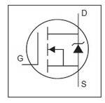
Secondly all your listed MosFet are N channel any one can be used. In my opinion IRFZ44/45/46 are best suited for you application you will find it easily and economical whereas P type MosFets are costly and hard to find
Lastly the symbol of MosFet in Datasheet explains itself
MosFet Symbol.jpg
Arrow pointing from Source pin to Gate is N channel
gate to be connected to the other end of resistance coming out of collector+emitter joint, you can use all/any of your listed N channel MosFets

- - - Updated - - -

ya ok sir , so what about a P & N channel mosfet number ?
@ John
you are right about 555 being totem pole output but it is not safe to drive any MosFet directly from pin 3 of 555 as user is using filamet lamps which tend to give inductive reactance which may lead to damaging the Oscillator and MosFet both
 
N-channel Mosfets have a drain that pulls a load close to ground. P-channel Mosfets have a drain that pulls a load close to the positive supply voltage.

I do not know which Mosfets are available in your country. One minute ago I simply looked in Google for P-Channel Mosfet Part Numbers and I found many lists from many manufacturers.

Use the NPN and PNP emitter-follower transistors to drive a Mosfet with high frequencies (for Pulse-Width-Modulation).

Did you notice that when the on-resistance is low then the output current can be higher? High voltage Mosfets have high on-resistance and low maximum current.
 
Yes very correct circuit, it is for cool and safe operation of MosFet With Filament lamps being inductive load, as you know MosFet are very sensitive devices which tend to burn/blow off, if not switched On/Off properly.
Secondly all your listed MosFet are N channel any one can be used. In my opinion IRFZ44/45/46 are best suited for you application you will find it easily and economical whereas P type MosFets are costly and hard to find
Lastly the symbol of MosFet in Datasheet explains itself
View attachment 103483
Arrow pointing from Source pin to Gate is N channel

- - - Updated - - -


@ John
you are right about 555 being totem pole output but it is not safe to drive any MosFet directly from pin 3 of 555 as user is using filamet lamps which tend to give inductive reactance which may lead to damaging the Oscillator and MosFet both


hmmm yaa its true . . no doubt :)
well i know about the symbol & too about some mosfet's precautions
theoritically but don't hv very much practical idea about what i read in books so thanks a lot again . .

for present , i just have to drive 5m white LED strips (china made) we use in diwali etc but your info about reactance is great & a guide for my further practice . . thanks buddy :)
 

What is the exact load current and how many White LEDs in series/parallel combination?????
that will help in helping you with proper components and schematic to be used
 
N-channel Mosfets have a drain that pulls a load close to ground. P-channel Mosfets have a drain that pulls a load close to the positive supply voltage.

I do not know which Mosfets are available in your country. One minute ago I simply looked in Google for P-Channel Mosfet Part Numbers and I found many lists from many manufacturers.

Use the NPN and PNP emitter-follower transistors to drive a Mosfet with high frequencies (for Pulse-Width-Modulation).

Did you notice that when the on-resistance is low then the output current can be higher? High voltage Mosfets have high on-resistance and low maximum current.


ohhhh yes yes yes i read i just noticed what you said & ya its true about the details & got it what i ve to do now based on your early suggestions :) thanks

sir you explained "Use the NPN and PNP emitter-follower transistors to drive a Mosfet with high frequencies (for Pulse-Width-Modulation)."

so please suggest a diagram close to your explanation here

- - - Updated - - -

What is the exact load current and how many White LEDs in series/parallel combination?????
that will help in helping you with proper components and schematic to be used


oh yaa very sure

well i ve to search its cover-bag for some of the parameters so ll tell you later about all that
but for now i measured the load current as 0.40 Amp.approx with 12volts 7 Ah battery (TP7)

About combinations i am not sure cause its all sealed smd type LEDs with smd resistors built-in within the path markikng 551

May be all are in parallel or a combinational one , no idea & number of LEDs here are 297

an equivalent link may help you

http://www.amazon.com/LEDwholesalers-Flexible-LED-Strip-300xSMD3528/dp/B002Q8V8DM#productDetails

- - - Updated - - -

this link resembles my device

http://www.ks-light.com/china-id307.html

mine is waterproof
 

For that much volts you can you any darling-ton transistors like TIP122 one will do with approximately 470E resistance between pin 3 of 555 and base of said transitor

- - - Updated - - -

For that much volts you can you any darling-ton transistors like TIP122 one will do with approximately 470E resistance between pin 3 of 555 and base of said transitor
 
For that much volts you can you any darling-ton transistors like TIP122 one will do with approximately 470E resistance between pin 3 of 555 and base of said transitor

- - - Updated - - -

For that much volts you can you any darling-ton transistors like TIP122 one will do with approximately 470E resistance between pin 3 of 555 and base of said transitor


hmm I SEE , so any equivalent number for TIP122 ???
 

You do not need the high voltage, high current and high current gain of a TIP122 darlington power transistor.
Almost ANY little transistor will turn on and off 400mA LEDs from a 12V battery if the base resistor value is calculated correctly and driven from an ordinary 555.
You also do not need a high power Mosfet.


yes sir,i applied a 2N3904 but i am getting an output lil.bit lower than direct supply & strip is not glowing up with its full brightness . .

With higher resistor values brightness was too low but with an only 10 ohm resistor the present brightness is close to original but not like original :( so unable to achieve a white bright light
Why didn't you look at the datasheet of the 2N3904 to see that its maximum allowed current is only 200mA and its performance above 100mA is poor?
The maximum output current of a 2N2222, 2N4401 and hundreds of other transistors is 600mA or more and will work much better. The base resistor should be 180 ohms.
 
Status
Not open for further replies.

Part and Inventory Search

Welcome to EDABoard.com

Sponsor

Back
Top