Continue to Site

Welcome to EDAboard.com

Welcome to our site! EDAboard.com is an international Electronics Discussion Forum focused on EDA software, circuits, schematics, books, theory, papers, asic, pld, 8051, DSP, Network, RF, Analog Design, PCB, Service Manuals... and a whole lot more! To participate you need to register. Registration is free. Click here to register now.

Question - micro timer IC

Status
Not open for further replies.

GH Crash

Member level 1
Joined
Aug 5, 2022
Messages
41
Helped
0
Reputation
0
Reaction score
2
Trophy points
8
Activity points
507
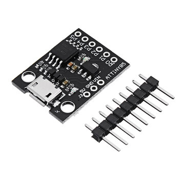
I have an idea floating around in my head but everything depends upon finding a micro size timer chip. The timer just has to turn on/off a MOSFET. By micro, I mean a chip smaller than a postage stamp.

Does anyone know of a micro size low voltage IC timer? All I need is the part number of such a timer, or where to I might find out more information about micro timers.


Thanks for any help you can give.

George
 

LMC555 - works from about 1 to 1.2V upwards.

Is precise timing vital? LMC555 is about +-1% repeatably accurate. If precision matters (I suspect not so much) use a capacitor specified for timing applications such as dielectric made from NP0 (C0G) or PPS, or polystyrene for very short times, otherwise sloppy X7R or woozy aluminium electrolytic dielectrics would do.

And, check resistor ppm for tight timing requirements - 100ppm is okay, 3,500 ppm maybe not so much.
 

1) Is it a fixed unchanging timeout ?

2) What triggers the timer ?

3) Accuracy of timing needed ?

4) Do you want a time of day event or just a fixed time to run the MOSFET
once triggered ?

An ATTINY85 should be able to handle this :

1661811113055.png


Clock accuracy -
1661812268598.png


Regards, Dana.
 
Last edited:

if you want really tiny but accurate, use a PIC10F200. Their clock is trimmed at the factory for accuracy and they are available in 6-pin SOT23 packages. With care you can implement several timers on on IC!

Brian.
 

LMC555 - works from about 1 to 1.2V upwards.

Is precise timing vital? LMC555 is about +-1% repeatably accurate. If precision matters (I suspect not so much) use a capacitor specified for timing applications such as dielectric made from NP0 (C0G) or PPS, or polystyrene for very short times, otherwise sloppy X7R or woozy aluminium electrolytic dielectrics would do.

And, check resistor ppm for tight timing requirements - 100ppm is okay, 3,500 ppm maybe not so much.
Thank you very much. I was unaware that the LCM555 might work. I will investigate it. I will also have to look to study up on X7R ad 'woozy aluminum electrolytic dielectrics.

George
1) Is it a fixed unchanging timeout ?

2) What triggers the timer ?

3) Accuracy of timing needed ?

4) Do you want a time of day event or just a fixed time to run the MOSFET
once triggered ?

An ATTINY85 should be able to handle this :

View attachment 178286

Clock accuracy - View attachment 178287

Regards, Dana.
Dana,
I might have mislead you in calling it a timer. It would have been more accurate to call it a count down timer.

No, not fixed but adjustable.

Timer triggered by manually operated switch.

Accuracy needed? Not much, +/- half second.

A time to run only.

Thanks for the information. I will definitely look at the ATTINY85.

George
--- Updated ---

if you want really tiny but accurate, use a PIC10F200. Their clock is trimmed at the factory for accuracy and they are available in 6-pin SOT23 packages. With care you can implement several timers on on IC!

Brian.
Thanks Brian. The smaller and lighter the better. I will look at the PIC10F200.

George
--- Updated ---

I've now have three candidates for an micro timer. Thanks very much for the suggestion. Now I will need time to study each of the suggested timers.
 
Last edited:

I should add that the PIC10F2xx series need to be programmed but that could be to your advantage because it adds to their versatility. You also need a simple programming device. Everything is very inexpensive and although it uses BASIC (a horrible language to use), a company called Oshonsoft sell a simple programming tool that not only helps you write the program but lets you test it (debug it!) on a PC before committing it to the IC itself. As a bonus, the IC can be reprogrammed if you want to change its operation or use it for a different task altogether.

The Oshonsoft package is at https://oshonsoft.com/pic10.php
If you haven't programmed an MCU before, don't be put off by the screen images, it is REALLY easy.

Brian.
 

    GH Crash

    Points: 2
    Helpful Answer Positive Rating
Here is possible code solution to the problem using mBlock. You drag and drop
the blocks into design area, config them, and mBlock generates the Arduino code
used to program ATTINY85.

The pot ranges the time from 0 to 1023 seconds, that range can be changed easily
just by scaling the V read. This is used to control the time MOSFET stays on.

To program the ATTINY85 one uses Arduino board as an in circuit programmer. Like a Nano or UNO
board.
1661856152808.png


Or use one of these boards and USB, programmer Arduino IDE (free).


If you want to count trigger pulses to control MOSFET on time thats easy to change
the above code. Same for adding a reset button if thats desired.

Proto looks something like this -

1661856318875.png


Regards, Dana.
 
Last edited:

    GH Crash

    Points: 2
    Helpful Answer Positive Rating
Thanks for all the good information. Give me some time to digest it then I may come back with some questions.

George
 

Hi,

I have my doubts that the breadboard circuit of post#7.
All the load current goes across the same GND lines that supply the ATtiny (BTW: is the ATtiny correctly supplied at all?)
Thus all the voltage drop across the GND line will hit the ATtiny. So ADC readings (...not capacitvely stabilized!) will be unstable .. maybe even the the microcontroller refuses to work reliably.

If we consider low supply voltage as well as high load current as in the other thread of the OP ..
A rearrangement of the components and additional decoupling could improve the situation.

Klaus
 

All the load current goes across the same GND lines that supply the ATtiny (BTW: is the ATtiny correctly supplied at all?)

ATTINY85 has its ground one column off not connecting its ground pin = error. Pic has
been corrected.

1661938473285.png


Yes, the load and the ATTINY85 ground must be common. However this is a protoboard,
in real design at edge of PCB is where normally the grounds would meet.

We do not yet know what the load current is, nor do we know what the load power rail is,
nor do we know type of load, if its inductive and needs snubber/catch diode, will advise
layout and other recommendations sequentially when this is provided.. Let alone T and V
and environmentals.......

Last note for OP, the mBlock code shows also button being de-bounced. Code could
also easily be changed to debounce trigger input if needed. Note also mBlock provides
Arduino code which you can then modify if you need access to registers, other special
setups. But it does not back edit into mBlock changes done this way. I use mBlock to do
fast simple stuff, C and C++ for the more involved stuff. All is good. Also many other
block languages each with their own special bent. Good news learn one you essentially
can work with all.

Regards, Dana.
 

Attachments

  • 1661938275503.png
    1661938275503.png
    378 KB · Views: 158
Last edited:

Hi,

Pic has
been corrected.
Now it makes more sense. Thanks.

We do not yet know what the load current is, nor do we know what the load power rail is,
True.
A lack of basic information.
My mistake: I had the values of the OP´s other thread in mind. But indeed it´s not clear whether both threads talk about the same application. If so .. both functions could easily combined in one microcontroller making the system even smaller and more versatile.

Klaus
 

GH Crash, here is an example, using mBlock, of a more sophisticated timer :


Regards, Dana.
 

Hi GH,

You've gone quiet... Everything going okay?

If you've been reading up on timers with loose requirements - such as yours are, I guess that by now you'll have realised that a microcontroller is utter overkill for such a simple function and even an incongruous/unhelpful suggestion for someone with your knowledge and requirements. BTW, if needs must, you can make a tolerable one-shot timer (bistable, multivibrator, etc.) with a couple of BJTs and a few passive components, again, no code needed, not beautiful but functional and helps to understand simplicity of goal.
 

1) We have 6'th graders now programming simple controllers with block programming,
for robot control. The example in post # 7 shows just how simple it is to do block
programming. And as you can see not too many parts involved. I work with folks who
dont realize, in their head, they have been programming micros for a long time if they
have been using calculators. Albeit a tad different than what folks think of as
programming these days. But all the principles are there, sequence of operations,
variables to hold intermediate and final results, even methods.....

2) Low end micros like the ATTINY85 have decent T and V timing error reduction, in case
you want your timer to be somewhat accurate. And thats just a pinprick in capability,
utility, flexibility.......

3) Micros these days are like pocket change, ubiquitous, tools getting easy to use,
some micros as cheap as dirt, its all good.

Watch a couple of video's on either mBlock or Scratch, lots of fun. Tons and tons of
online forums and help. Driven by an insatiable desire to build back better.....:)
There is even programming using flow charts, Flowcode, Stuff for web work, Nodered,
and Tuniot where you can get a server going in a handful of minutes. The good news
once you learn one of them they are all similar in a broad sense.

Life is good.


Regards, Dana.
 
Last edited:

Found an astable/bistable/monostable tutorial that is reputable and easy to follow. Not to use any of those for your circuit, I don't mean that, but it's just interesting to see how such things can be made.

BJT multivibrators
 
My apologies to everyone for my silence. I've been off doing some micro carbon fiber construction stuff.

Ive looked at data sheets and reread all your posts.

One of the things that I hoped to figure out on my own was how, and on which timer, to make the time interval adjustable.
The way I envision things is that:
1. The 'run' time is adjusted by some means
2. A manual switch turns on both the timer and load
3. The timer runs for the set time and then turns off the load

The load will be a small brushed DC motor drawing less than two amps.
The power source, if I can find the right ones, will be solar cells. Voltage and current unknown at this time.
'Run' time will be in the range of 10 seconds to 300 seconds, +/- 1sec accuracy sufficient.
It is imperative that the entire circuit be as light as possible, less than half a gram.

Klaus. This is a completely separate project than the one I ask for help with. This project is not concerned with controlling the load's output power, only in turning it off at a certain time.
--- Updated ---

My apologies to everyone for my silence. I've been off doing some micro carbon fiber construction stuff.

Ive looked at data sheets and reread all your posts.

One of the things that I hoped to figure out on my own was how, and on which timer, to make the time interval adjustable.
The way I envision things is that:
1. The 'run' time is adjusted by some means
2. A manual switch turns on both the timer and load
3. The timer runs for the set time and then turns off the load

The load will be a small brushed DC motor drawing less than two amps.
The power source, if I can find the right ones, will be solar cells. Voltage and current unknown at this time.
'Run' time will be in the range of 10 seconds to 300 seconds, +/- 1sec accuracy sufficient.
It is imperative that the entire circuit be as light as possible, less than half a gram.

Klaus. This is a completely separate project than the one I ask for help with. This project is not concerned with controlling the load's output power, only in turning it off at a certain time.

George
 

If you use an Arduino Nano instead of the ATTINY85 it has a xtal onboard which
will get you the accuracy you need. ~ $3 board.

1662645680469.png


Then just modify the block code shown in post #7 to scale the pot V read to the
time you want.


Regards, Dana.
 

Hi,
'Run' time will be in the range of 10 seconds to 300 seconds, +/- 1sec accuracy sufficient.
some values to do some math on. (y)

1 second of 300 is about 0.3% or 3000 ppm
you need special resistors if you want this accuracy. even harder to find that accurate capacitors.
But then you need a circuit (amplifier, comparator...) with according accuracy on threshold levels and leakage currents.

This all calls for a digital system using an XTAL clock.... (3000ppm accuracy is a very relaxed requirement for an XTAL)

Klaus
 
Hi,

some values to do some math on. (y)

1 second of 300 is about 0.3% or 3000 ppm
you need special resistors if you want this accuracy. even harder to find that accurate capacitors.
But then you need a circuit (amplifier, comparator...) with according accuracy on threshold levels and leakage currents.

This all calls for a digital system using an XTAL clock.... (3000ppm accuracy is a very relaxed requirement for an XTAL)

Klaus
OK. Let's make it +/- 1%.

Right now I'm trying to figure out if a LMC555 or a microprocessor would be the better way to go. (The exact microprocessor hasn't been determined yet, something SOIC size or smaller.
 

Status
Not open for further replies.

Part and Inventory Search

Welcome to EDABoard.com

Sponsor

Back
Top