Continue to Site
Follow along with the video below to see how to install our site as a web app on your home screen.
Note: This feature may not be available in some browsers.
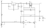
It is small, but I can see all the essential elements of a full bridge power supply.
But I do have a couple of observations:
1) For the inrush limiter you are using a NTC thermistor. At full load, the losses of the thermistor may be too large. You may want to use a relay to bypass the thermistor after a couple of seconds.
2) The supply has positive and negative outputs. But you are taking the feedback from only the positive output. If the loads are reasonably balanced this may be no problem. But what happens if, for instance, the negative load is completely removed while the positive is at full load? An over voltage condition will occur. You may want to add some monitoring circuit on the negative load, to either shutdown everything or add a "bleed" load.
3) How about temperature? You may want to add a thermistor to sense the heatsink temperature and start up a fan or even shut everything down.
4) Fuses? I don't see any fuses.
5) Lastly and this is optional: I would put status LEDs. At the very least one LED on each output voltage. If the temperature sensing is added, another LED to alert that condition. Of course additional monitoring conditions (overcurrent, AC OK, etc) may be added with additional circuitry.
Looks much better!
You may want to start building sections of it to test it.
The LM393 has an open collector on its output. You require, for the real circuit, a pullup resistor to V+
I don't understand what you are doing with M9 and M10.
I see that you would like to create a discrete AND circuit, but if the gates of the two mosfets are tied together..this wouldn't work, correct?

I haven't reviewed the PWM controller's full specs, but many controllers for push-pull or full bridge topologies divide the master clock in half.
should be the same for the full bridge.
Cross regulation will be a tremendous problem whenever the loads are not fully matched and one of the inductors goes into discontinuous mode while the other remains in continuous mode. The transfer function varies as the inductors cross boundaries.
So no, if there is an opportunity for that scenario to occur, your proposed scheme will not work.
-Are the currents in both outputs equal? Always?
-Which of the two outputs is most important?
I believe there is a technique which utilizes a coupled inductor...but it has been a long while when I read that.