Continue to Site

Welcome to EDAboard.com

Welcome to our site! EDAboard.com is an international Electronics Discussion Forum focused on EDA software, circuits, schematics, books, theory, papers, asic, pld, 8051, DSP, Network, RF, Analog Design, PCB, Service Manuals... and a whole lot more! To participate you need to register. Registration is free. Click here to register now.

Power amplification to control a DC motor 12V

Status
Not open for further replies.

Houssem85

Newbie level 5
Joined
Jan 18, 2014
Messages
9
Helped
0
Reputation
0
Reaction score
0
Trophy points
1
Activity points
67
Hello ,

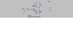
I designed a power amplifier so that it plays the role of interface between my STM32 microcontroller and a pump (12V 1A).
This circuit is a good power amplifier which helped me to control this motor from the microcontroller which inject into the input a PWM 3.3V.

My question here is this:
I want to provide a more comfortable current (and voltage ) to the motor, so I change R1, or R9 or R6... ? and Why?

Vcc = 12V

Please give me a change in the circuit, so that the motor runs better.

Can you help me ??

Here attached the circuit of the power amplifier.


power amplifier.jpg
 

Apply your PWM signal from the micro to the TIP31 directly. Emitter grounded. PWM into base via resistor. Motor connected from power supply + to collector of the TIP.
Remember to put a reverse diode across motor for commutation. TIP31 is rated for 3A , so it would work , but a higher current device would be preferable.
Depending on the current available from your micro pin , you may need another transistor to make a Darlington configuration , like the tip/3055 in your drawing.
You could also use a logic level mosfet in place of the bipolar , which would be a better idea anyway I think.
Neddie

- - - Updated - - -

Simple schematic attached

- - - Updated - - -

Sorry , small mod , R2
 

Attachments

  • pwm.jpg
    pwm.jpg
    57.7 KB · Views: 80
Hi neddie,

If I use this circuit is that in this case the microcontroller is protected against high voltage or current inerse?

With regards.
 

The micro will be fine , the base resistor will offer protection in the case that the transistors go short to supply. Very unlikely.
I'm not sure what you mean by "current inerse".
Don't forget the diode though , that is important. I should have asked earlier but what frequency is your PWM?
 

The micro will be fine , the base resistor will offer protection in the case that the transistors go short to supply. Very unlikely.
I'm not sure what you mean by "current inerse".
Don't forget the diode though , that is important. I should have asked earlier but what frequency is your PWM?

I mean "current inverse" :)

The frequency pf the PWM is (1/0.02). Can you propose a better frequency for better motor operation ??

Now if I use my first circuit, It is important to use a diode parallel with the motor ?? why ?

with regards.
 

PWM = 50hz. That is very low.
I'd start at say 10KHz and see how the transistors fare. Simulation shows it should be fine up to 25KHz no problem , but just check.
If it's working at 10KHz , increase it until it's above audible range. You don't have to it's up to you. 1KHz will work.
The pwm frequency has to be high enough for the motors inductance to behave as intended. It averages out the current , so 50% duty cycle is = 6V. If the frequency is to low the inductor current will ramp up to maximum and down to 0.
The diode is there to circulate the current when the switch turns off. Just make sure you have it the right way around. Cathode to the supply.
Cheers
Neddie
 
Status
Not open for further replies.

Similar threads

Part and Inventory Search

Welcome to EDABoard.com

Sponsor

Back
Top