Welcome to our site! EDAboard.com is an international Electronics Discussion Forum focused on EDA software, circuits, schematics, books, theory, papers, asic, pld, 8051, DSP, Network, RF, Analog Design, PCB, Service Manuals... and a whole lot more! To participate you need to register. Registration is free. Click here to register now.
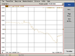
Hi, I have designed a RF amp at frequency 5.3GHz. Would like to know what is the root cause for the ripple effect along the band? Is it the unstable of the amplifier? or the not matching? or there is too much reflection?
It seems to me this effect could be due to a long (referred to lambda) poorly matched transmission line. Is your network analyzer calibrated at the end of the connecting cables ? Can't you measure S11 and/or S22 ?
It seems to me this effect could be due to a long (referred to lambda) poorly matched transmission line. Is your network analyzer calibrated at the end of the connecting cables ? Can't you measure S11 and/or S22 ?
This site uses cookies to help personalise content, tailor your experience and to keep you logged in if you register.
By continuing to use this site, you are consenting to our use of cookies.