Continue to Site

Welcome to EDAboard.com

Welcome to our site! EDAboard.com is an international Electronics Discussion Forum focused on EDA software, circuits, schematics, books, theory, papers, asic, pld, 8051, DSP, Network, RF, Analog Design, PCB, Service Manuals... and a whole lot more! To participate you need to register. Registration is free. Click here to register now.

[ARM] Need help for LPC2148 Adc code

Status
Not open for further replies.

arunbharathi.arasu

Full Member level 2
Joined
Feb 28, 2013
Messages
134
Helped
7
Reputation
14
Reaction score
6
Trophy points
1,298
Location
Chennai, Tamil Nadu, India
Activity points
2,151
hai Friends,
I have problem in LPC2148 ADC code.
I have written code in keil compiler,the ADC output data will displaly in to UART
Here i post ADC initialization code and ADC read code.
please check it out and help me...
Code:
#include<lpc214x.h>


void adc0_init(void)
{


 // Enable ADC0
 AD0CR &= 0x00000000;		// Clear All Bit Control
 AD0CR |= 0x00000400;		// ADC Clock = VPB(PCLK) / 8
 AD0CR &= 0xFFFEFFFF;		// Busrt = 0			- Conversions are software controlled and reguire 11 clocks
 AD0CR &= 0xFFF1FFFF;		// CLKS  = 000		- 10Bit : 11 Cycle Clock Conversion
 AD0CR |= 0x00200000;		// PDN   = 1			- Active ADC Module
}


unsigned int adc0_channel_1(void)
{
 unsigned int	val;
 // Initial AD0.1 (P0.28) By Set PINSEL1[25:24=01] 
 // xxxx xx01 xxxx xxxx xxxx xxxx xxxx xxxx
 PINSEL1 |= 0x01000000;	   //  channel 1 in adc0


 AD0CR &= 0xffffff00;
 AD0CR |= 0x00000002;		// Select ADC = AD0.1  
  // START = 001 = Start Conversion Now
 AD0CR |= 0x01000000;
 // Wait ADC Conversion to Complete and Read A/D Data Register
 //uart0_putch('6');


 while(!(AD0GDR & 0X80000000));
 // Shift ADC Result to Integer
 val = (unsigned int)(AD0DR1 >> 6) & 0x000003FF;
 AD0CR &= 0xF8FFFFFF;	    //STOP THE ADC
 return (val);
}
 

what happed what is result?

- - - Updated - - -

will you post full code.

- - - Updated - - -

this code will help you

Code:
/*		Clock Settings:
		FOSC	>>	12MHz (onboard)
		PLL		>>	M=5, P=2
		CCLK	>>  60MHz
		PCLK	>>  15MHz 
*/
#include  <lpc214x.h>	 //Includes LPC2148 register definitions

#define Fosc            12000000                    
#define Fcclk           (Fosc * 5)                 
#define Fcco            (Fcclk * 4)                 
#define Fpclk           (Fcclk / 4) * 1              

#define  UART_BPS	9600			 //Set buadrate here

void DECtoASCII(unsigned int Data);
void Delay(unsigned char Ticks);
void Init_UART0(void);
void UART0_SendByte(unsigned char data);
void ADC_Init(void);
void  UART0_SendByte(unsigned char data);

unsigned int ADC_Data1=0;
unsigned int ADC_Data2=0;
unsigned char Temp[4];
double Data;


void DECtoASCII(unsigned int Data)		 //This function converts decimal data into ASCII
{
 Temp[3]='V';
 Temp[2]=(Data % 10) + 48; 
 Temp[1]='.';
 Temp[0]=(Data / 10) + 48;
}


void  Delay(unsigned char Ticks)	  //Function to generate small delay
{  
 unsigned int i=0;
 if(Ticks==0)
 {
  Ticks=1;
 }

 for(;Ticks>0;Ticks--)
 for(i=0; i<60000; i++);
}

void  Init_UART0(void)				 //This function setups UART0. Refer datasheet for more details
{  
   unsigned int Baud16;
   U0LCR = 0x83;		            // DLAB = 1
   Baud16 = (Fpclk / 16) / UART_BPS;  
   U0DLM = Baud16 / 256;							
   U0DLL = Baud16 % 256;						
   U0LCR = 0x03;
}

void  UART0_SendByte(unsigned char data)   //Function to send a byte on UART0
{  
   U0THR = data;				    
   while( (U0LSR&0x40)==0 );	    
}

void  UART0_SendStr(unsigned char *str)	 //A function to send a string on UART0
{  
   while(1)
   {  
      if( *str == '\0' ) break;
      UART0_SendByte(*str++);	    
   }
}


void ADC_Init()			//This function inits ADC peripheral
{
 AD0CR=0x00200E00;		// SEL = 1 	ADC0 channel 1	Channel 1
						// CLKDIV = Fpclk / 1000000 - 1 ;1MHz
						// BURST = 0   // CLKS = 0  // PDN = 1 
 						// START = 1   // EDGE = 0 (CAP/MAT)
} 
                           

unsigned char ADC_Conversion(unsigned char Channel)
{
 unsigned int Temp=0;
 AD0CR = (AD0CR&0xFFFFFF00) | Channel;			   //Select AD0.1 for conversion
 AD0CR|=(1 << 24);							   //Trigger conversion
 while((AD0DR1&0x80000000)==0);			   //Wait for the conversion to be completed
 Temp = AD0DR1;						   //Store converted data
 Temp = (Temp>>8) & 0x00FF;
 return(Temp);
}


int main(void)
{  
 PINSEL0 = 0x00000005;		// Enable UART0 Rx and Tx pins
 PINSEL1 = 0x05000000;		// Enable AD0.1 and AD0.2
 PINSEL2=  0x00000000;

 Init_UART0();
 ADC_Init();
  
 while(1)	
 { 
  AD0CR = (AD0CR&0xFFFFFF00)|0x02;			   //Select AD0.1 for conversion
  AD0CR|=(1 << 24);							   //Trigger conversion
  while((AD0DR1&0x80000000)==0);			   //Wait for the conversion to be completed
  ADC_Data1 = AD0DR1;						   //Store converted data
  ADC_Data1 = (ADC_Data1>>8) & 0x00FF;
  
  Delay(1);

  AD0CR = (AD0CR & 0xFFFFFF00) | 0x04 ;		   //Select AD0.2 for conversion
  AD0CR|=(1 << 24);							   //Trigger conversion
  while((AD0DR2&0x80000000)==0);			   //Wait for the conversion to be completed
  ADC_Data2 = AD0DR2;						   //Store converted data
  ADC_Data2 = (ADC_Data2>>8) & 0x00FF;
  
  //UART0_SendByte('\r');						   //Send carriage return to display data on new line
  
  Data=(double)ADC_Data1 * 0.0129 * 10.0;	   //Convert Digital data to represent Analog value
  											   //(x/255)*3.3=0.0129x 
  DECtoASCII((unsigned int)Data);
  UART0_SendStr("AN1=");
  UART0_SendStr(Temp);
  UART0_SendByte(' ');

  Data=(double)ADC_Data2 * 0.0129 * 10.0;
  DECtoASCII((unsigned int)Data);
  UART0_SendStr("AN2=");
  UART0_SendStr(Temp);
  UART0_SendByte('\n');
  
  
 }
 
}

just config as per requirement
 

I posted full code empic,
please check it.
Code:
#include<lpc214x.h>
#include"adc.h"

//////////////////////////////////////ADC INITIALIZATION AND ADC READ DATA
void adc0_init(void)
{

 // Enable ADC0
 AD0CR &= 0x00000000;		// Clear All Bit Control
  AD0CR &= 0x00200E00;
	AD0CR |= 0x00000400;		// ADC Clock = VPB(PCLK) / 8
 AD0CR &= 0xFFFEFFFF;		// Busrt = 0			- Conversions are software controlled and reguire 11 clocks
 AD0CR &= 0xFFF1FFFF;		// CLKS  = 000		- 10Bit : 11 Cycle Clock Conversion
 AD0CR |= 0x00200000;		// PDN   = 1			- Active ADC Module
}


unsigned int adc0_channel_1(void)
{
 unsigned int	val;
 // Initial AD0.1 (P0.28) By Set PINSEL1[25:24=01]
 // xxxx xx01 xxxx xxxx xxxx xxxx xxxx xxxx

	PINSEL1 |= 0x01000000;	   //  channel 1 in adc0
 AD0CR &= 0xffffff00;
 AD0CR |= 0x00000002;		// Select ADC = AD0.1
  // START = 001 = Start Conversion Now
  	AD0CR |= 0x01000000;
 // Wait ADC Conversion to Complete and Read A/D Data Register
 //uart0_putch('6');

 while((AD0DR1 & 0X80000000)== 0);
 // Shift ADC Result to Integer
 val = (unsigned int)(AD0DR1 >> 6) & 0x000003FF;
 AD0CR &= 0xF8FFFFFF;	    //STOP THE ADC
 return (val);
}

////////////////////////////////////////////////////////////////////


////////////////////////////////////////////UART
void uart0_init()
{
 PINSEL0 =0x00000005;
 U0LCR =0X80;
 U0DLL =97;
 U0LCR =0X03;
}

void uart0_putch(unsigned char val)
{
 while(!(U0LSR & 0x20));
 U0THR =val;
}

unsigned char uart0_getch()
{
 while(!(U0LSR & 0x01));
 return(U0RBR);
}

void uart0_puts( char *stringptr)
{
  while (*stringptr)
   uart0_putch(*stringptr++);
}

//////////////////////////////////////////////

///////////////////////////////////////////////////NUMERIC TO ASCIIFUNCTION
void adc_int(unsigned int adc_value)
{
 unsigned int adc_arr[10],adc_val;
	char adc1;

 for(adc_val=1;adc_val<5;adc_val++)
 {
  adc_arr[adc_val] = adc_value%10;
  adc_value  = adc_value/10;
 }

 for(adc_val=4; adc_val!=0 ; adc_val--)					//sending data to adc
 {
	 adc1=(char)adc_arr[adc_val]+48;
  uart0_putch(adc1);
 }
}
///////////////////////////////////////
void main_delay(unsigned int val)			//DELAY FUNCTION
{
 unsigned int main_i,main_j;
 for(main_i=0;main_i<val;main_i++)
  for(main_j=0;main_j<1000;main_j++);
}
/////////////////////////////////////////////////////////MAIN FUNCTION
int main()
{
 unsigned int ad1;
 uart0_init();
 uart0_puts("SamCys Technologies\r");
 adc0_init();			  //INITIALIZES THE ADC
 uart0_puts("voltage:\r");

 while(1)
 {
    ad1=adc0_channel_1();			   //GET THE DATA FROM CHANNEL1
    adc_int(ad1);					   //DISPLAY THE ADC VALUE ON LCD
	main_delay(1000);

 }
 

and post adc.h file also

- - - Updated - - -

@arunbharathi.arasu
this code is working and here i have post screen shot
and you have not mention what is your problem?
Untitled.png
 

adc.h file functions are pasted in same file.
And my problem is,Adc conversion cannot working.I din't use any hardware i checked only by proteus.
Did you modify the code?
 

no i don't have modified your code.
 

yes i had checked with hardware and i was posted screen shot of hyper terminal in post #4 and was worked.
 

hi embpic,
Ya i have checked in keil simulation it is working,but in proteus it is not working.
Now i don't have hardware. After i bought i will check.
thank you.

- - - Updated - - -

hi venkadesh,
i already posted my full keil code in post #3.
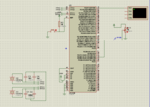
Here i posted proteus design.
Capture.PNG
 

hi friends ,,

can you explain about the setting of CLK DIV values for ADCR register ??

thanking you in advance
 

hi friends,

i tried to compile the sample code posted here with simple modification.i got the output in 8 bit instead of 10 bit adc result.

in proteus lpc2124 is used..

kindly help me with this.

Code:
#include "lpc21xx.h"
#define Fosc 12000000
#define Fcclk (Fosc*5)
#define Fcco (Fcclk*4)
#define Fpclk (Fcclk/4)
#define UART_BPS 9600     //SET BAUD RATE
//function prototype

void DECtoASCII(unsigned int data);
void Delay(unsigned char Ticks);
void init_UART0(void);
void UART0_Sendbyte(unsigned char data);
void UART0_Sendstr(unsigned char *str);
void ADC_init(void);
unsigned char ADC_Conversion(unsigned char channel);
////////////////

unsigned int ADC_Data1=0;
unsigned int ADC_Data2=0;
unsigned char TEMP[5];
double data;

///////////////

void DECtoASCII(unsigned int data)
{ 
	signed int i,local[5]={0,0,0,0,0};
	for(i=0;i<4;i++)
	 { local[i]=data%10;
		data= data/10;
	 }
	for(i=4;i>=0;i--)
	 { 
		 UART0_Sendbyte(local[i]+48);
		 
		 	 }
	 
	 
}
void Delay(unsigned char Ticks)
{
	unsigned int i;
  	if(Ticks==0)
		{
   		Ticks=1;
		}
	for(;Ticks>0;Ticks--)
	   {
      for(i=0;i<60000;i++);
	   }
	
}
void init_UART0(void)
{
	unsigned int Baud16;
	U0LCR=0X83;
	Baud16=(Fpclk/16)/9600;
	U0DLM=Baud16/256;
	U0DLL=Baud16%256;
	U0LCR=0X03;
	
}
 
void UART0_Sendbyte(unsigned char data)
{
	U0THR=data;
	while((U0LSR&0X40)==0);
}


void UART0_Sendstr(unsigned char *str)
{
	while(*str)
	{
		UART0_Sendbyte(*str++);
	}
		
}
void ADC_init(void)
  { 
		//PINSEL0=0X01000000; //AD0.1 PIN SELECTED
		ADCR&=0X00000000;
		ADCR|=0X00000E00;   //CLKDIV=PCLK/(ADCCLK-1) =15/1000000-1   ADCCLK=E
		ADCR&=0XFFF1FFFF;   //NO BURST IE BURST=0; SOFTWARE CONTROLLED

		ADCR&=0XFF3FFFFF;   //TEST 1:0 00 NORMAL MODE
		ADCR&=0XF7FFFFFF;   //EDGE =0 CONVERSION ON FALLING EDGE
		ADCR|=0X00200000;   //PDN=1 ACTIVE ADC MODULE
	}
	

unsigned char ADC_Conversion(unsigned char channel)
{
	unsigned int temp=0;
	ADCR=((ADCR&0XFFFFFF00)|channel);
	
	ADCR|=(1<<24);
	while((ADDR&0X80000000)==0);//wait for the conversion to complete
	//temp=ADDR;
	temp=(unsigned int)(ADDR>>6)&0x03ff;
	return temp;
}

int main()
{ unsigned int val;
	PINSEL0=0X05 ;// enable UART0 RX AND TX PINS
	PINSEL1=0X05; //ENABLE AD0.1 AND AD0.2
	PINSEL2=0;
	VPBDIV=0X01;//15 MHZ
	init_UART0();
	ADC_init();
	  while(1)
		{
			UART0_Sendstr("ADC");
			val=ADC_Conversion(1);
			DECtoASCII(val);
		}
	   
	
}
 

Status
Not open for further replies.

Similar threads

Part and Inventory Search

Welcome to EDABoard.com

Sponsor

Back
Top