jegues
Member level 3
Buck Converter Design for PMDC Motor
Introductory Notes: The design article followed in this post can be found here: **broken link removed**
This circuit will be used for a motor controller.
The batteries used to power the motor are Lithium Polymer batteries manufactured by GBS batteries. The batteries have sixteen 3.6V cells connected in series to have a rated voltage of 55V and a capacity of 60Ah.
The motor is a permanent magnet brushed DC motor from Motenergy, model part number ME0708. The motor has a lead to lead resistance of 0.01Ω, and a lead to lead inductance of 0.055mH at 120Hz. The motor is rated for 48V and 100A, but can handle up to 300A for one minute, and has maximum peak torque of 37.8 Nm and maximum rotor speed of 5000rpm.
This design will cover a particular stepdown regulator topology, that is, one with a fixed switching frequency, PWM and operation in CCM.
Design
Four design parameters are required:
Input Voltage Range
Regulated Output Voltage
Maximum Output Current
Switching Frequency
The figure below illustrates the basic topology we will be using,
For our design, the four main design parameters are as follows:
\[50V < V_{in} < 55V\]
\[V_{out} = 48V\]
\[I_{outmax} = 300A\]
\[f_{sw} = 20kHz\]
Inductor Selection
Calculating the inductor value is the most critical component when designing a stepdown switching converter.
First we assume we are operating in CCM with ideal switches an ideal diode:
\[L = (V_{inmax}-V_{out})*\frac{V_{out}}{V_{inmax}}*\frac{1}{f_{sw}}*\frac{1}{LIR*I_{outmax}}\]
Where LIR is the inductor current ratio expressed as a percentage of Iout.
The value of LIR represents a tradeoff between efficiency and load-transient response. An LIR = 0.3 represents a good trade off between the two.
This gives an L = 3.39uH, therefore we select,
\[ L = 3.3uH\]
From this the peak inductor current can be calculated,
\[I_{peak} = I_{outmax} + \frac{I_{ripple:L}}{2}, \text{ where}\]
\[ I_{ripple:L} = LIR * I_{outmax}\]
This yields,
\[ I_{peak} = 346.2A\]
Thus, when selected an inductor we should select one with a slightly higher saturation-current rating. Let's use a 20% margin, yielding,
\[ I_{sat} = 432A\]
Also, to minimize power loss, an inductor with the lowest maximum DCR specification will be selected.
Output Capacitor Selection
Output capacitance is required to minimize the voltage overshoot and ripple present at the output of a stepdown converter.
The problem of overshoot requires that the output capacitor is large enough to prevent stored inductor energy from launching the output above the specified maximum output voltage. Output voltage overshoot can be calculated using the following equation:
\[ V_{ripple} = \left(\sqrt{V_{out}^{2} * \frac{L(I_{outmax} + \frac{ I_{ripple:L}}{2})^{2}}{C_{o}}}\right) - V_{out}\]
Rearranging this equation yields,
\[C_{o} = \frac{L \left( I_{outmax} + \frac{ I_{ripple:L}}{2} \right)^{2}}{\left( V_{ripple} + V_{out} \right)^{2} - V_{out}^{2}}\]
If we allow for an output ripple that is 20% of the output voltage,
\[ V_{ripple} = 0.2 * V_{out} = 9.6V\]
This yields an output capacitance of,
\[ C_{o} = 390.33uF\]
If we add the typical capacitor value tolerance to this (i.e. 20%) we get a practical value for the output capacitance of,
\[C_{o} = 1.2 * 390.33uF = 468.4uF\]
Therefore we select,
\[ C_{o} = 470uF\]
The resulting output ripple due to the capacitance alone is given by,
\[V_{ripple:cap} = \frac{1}{2C_{o}}*\frac{(V_{inmax} - V_{out})}{L} * \left( \frac{V_{out}}{V_{inmax}} *\frac{1}{f_{sw}} \right)^{2} = 4.3V\]
The ESR of the output capacitor dominates the output voltage ripple. The ammount can be calculated as follows:
\[V_{ripple:ESR} = I_{ripple:L} *ESR_{C_{o}}\]
Adding the two ripple component (i.e. capacitor and ESR) we find the total output voltage ripple for the buck converter:
\[V_{ripple ut} = \frac{1}{2C_{o}}*\frac{(V_{inmax} - V_{out})}{L} * \left( \frac{V_{out}}{V_{inmax}} *\frac{1}{f_{sw}} \right)^{2} + I_{ripple:L} *ESR_{C_{o}} \]
Rearranging this to solve for the ESR yields,
\[ESR_{C_{o}} = \frac{1}{ I_{ripple:L}} * \left( V_{rippleut} - \frac{1}{2C_{o}}*\frac{(V_{inmax} - V_{out})}{L} * \left( \frac{V_{out}}{V_{inmax}} *\frac{1}{f_{sw}} \right)^{2}\right)\]
Thus using the desired output voltage ripple and the output capacitance value, one can calculate a maximum ESR. To achieve the desired output voltage ripple, we must select a capacitance with ESR lower than the one calculated above, with a capacitance greater or equal to 470uF.
Input Capacitor Selection
The input capacitors ripple rating dictates its value and size, and the following equation calculates how much ripple current the input capacitor must be able to handle:
\[I_{ripple:C_{in}} = I_{outmax} \frac{ sqrt{ V_{out}(V_{inmin}-V_{out})}}{V_{inmin}} \]
From this we calculate,
\[ I_{ripple:C_{in}} = 58.8A \]
The input capacitance required for a step down converter depends on the impedance of the input power source.
For common laboratory power supplies, 10uF - 20uF of capacitance per ampere of output current is usually sufficient.
So,
\[C_{in} = I_{ripple:C_{in}} * 10uF = 587.88uF\]
Select,
\[ C_{in} = 570uF\]
Diode Selection
Power dissipation is the limiting factor when choosing a diode. The worst-case average power can be calculated as follows:
\[P_{DIODE} = \left( 1 - \frac{V_{out}}{V_{inmax}} \right)*I_{outmax}*V_{D} = 26.73W\]
Where it is assumed that, \[V_{D} = 0.7V\]
Simulation
After this design process I decided to try and simulate and simulate the resulting circuit to view the results. I decided to neglect the LC filter at the input for now and just focus on the buck converter portion of the circuit.
Here is the link for the falstad circuit simulation: https://tinyurl.com/buckconverterdesignsimulation
Click the link above and a java applet will run and open the circuit I've simulated.
It appears as though I must have made some mistakes or overlooked certain things throughout the design process, as I did not obtain the results I was expecting.
Questions
Does anyone see anything I overlooked throughout my design, or any calculation errors? I'm trying to figure out why my design failed so miserably!
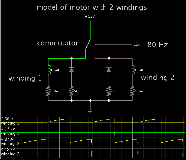
What is the appropriate way to model the motor as my load? I only have information regarding Resistance L-L = 0.01Ω and its L-L Inductance at 120Hz is 0.0550mH.
I have entered all of my design equations into a simple MathCAD program so changing the design parameters to obtain new results will take me very little time.
Thanks for reading and thanks for all your help!
Introductory Notes: The design article followed in this post can be found here: **broken link removed**
This circuit will be used for a motor controller.
The batteries used to power the motor are Lithium Polymer batteries manufactured by GBS batteries. The batteries have sixteen 3.6V cells connected in series to have a rated voltage of 55V and a capacity of 60Ah.
The motor is a permanent magnet brushed DC motor from Motenergy, model part number ME0708. The motor has a lead to lead resistance of 0.01Ω, and a lead to lead inductance of 0.055mH at 120Hz. The motor is rated for 48V and 100A, but can handle up to 300A for one minute, and has maximum peak torque of 37.8 Nm and maximum rotor speed of 5000rpm.
This design will cover a particular stepdown regulator topology, that is, one with a fixed switching frequency, PWM and operation in CCM.
Design
Four design parameters are required:
Input Voltage Range
Regulated Output Voltage
Maximum Output Current
Switching Frequency
The figure below illustrates the basic topology we will be using,
For our design, the four main design parameters are as follows:
\[50V < V_{in} < 55V\]
\[V_{out} = 48V\]
\[I_{outmax} = 300A\]
\[f_{sw} = 20kHz\]
Inductor Selection
Calculating the inductor value is the most critical component when designing a stepdown switching converter.
First we assume we are operating in CCM with ideal switches an ideal diode:
\[L = (V_{inmax}-V_{out})*\frac{V_{out}}{V_{inmax}}*\frac{1}{f_{sw}}*\frac{1}{LIR*I_{outmax}}\]
Where LIR is the inductor current ratio expressed as a percentage of Iout.
The value of LIR represents a tradeoff between efficiency and load-transient response. An LIR = 0.3 represents a good trade off between the two.
This gives an L = 3.39uH, therefore we select,
\[ L = 3.3uH\]
From this the peak inductor current can be calculated,
\[I_{peak} = I_{outmax} + \frac{I_{ripple:L}}{2}, \text{ where}\]
\[ I_{ripple:L} = LIR * I_{outmax}\]
This yields,
\[ I_{peak} = 346.2A\]
Thus, when selected an inductor we should select one with a slightly higher saturation-current rating. Let's use a 20% margin, yielding,
\[ I_{sat} = 432A\]
Also, to minimize power loss, an inductor with the lowest maximum DCR specification will be selected.
Output Capacitor Selection
Output capacitance is required to minimize the voltage overshoot and ripple present at the output of a stepdown converter.
The problem of overshoot requires that the output capacitor is large enough to prevent stored inductor energy from launching the output above the specified maximum output voltage. Output voltage overshoot can be calculated using the following equation:
\[ V_{ripple} = \left(\sqrt{V_{out}^{2} * \frac{L(I_{outmax} + \frac{ I_{ripple:L}}{2})^{2}}{C_{o}}}\right) - V_{out}\]
Rearranging this equation yields,
\[C_{o} = \frac{L \left( I_{outmax} + \frac{ I_{ripple:L}}{2} \right)^{2}}{\left( V_{ripple} + V_{out} \right)^{2} - V_{out}^{2}}\]
If we allow for an output ripple that is 20% of the output voltage,
\[ V_{ripple} = 0.2 * V_{out} = 9.6V\]
This yields an output capacitance of,
\[ C_{o} = 390.33uF\]
If we add the typical capacitor value tolerance to this (i.e. 20%) we get a practical value for the output capacitance of,
\[C_{o} = 1.2 * 390.33uF = 468.4uF\]
Therefore we select,
\[ C_{o} = 470uF\]
The resulting output ripple due to the capacitance alone is given by,
\[V_{ripple:cap} = \frac{1}{2C_{o}}*\frac{(V_{inmax} - V_{out})}{L} * \left( \frac{V_{out}}{V_{inmax}} *\frac{1}{f_{sw}} \right)^{2} = 4.3V\]
The ESR of the output capacitor dominates the output voltage ripple. The ammount can be calculated as follows:
\[V_{ripple:ESR} = I_{ripple:L} *ESR_{C_{o}}\]
Adding the two ripple component (i.e. capacitor and ESR) we find the total output voltage ripple for the buck converter:
\[V_{ripple
ut} = \frac{1}{2C_{o}}*\frac{(V_{inmax} - V_{out})}{L} * \left( \frac{V_{out}}{V_{inmax}} *\frac{1}{f_{sw}} \right)^{2} + I_{ripple:L} *ESR_{C_{o}} \]Rearranging this to solve for the ESR yields,
\[ESR_{C_{o}} = \frac{1}{ I_{ripple:L}} * \left( V_{ripple
ut} - \frac{1}{2C_{o}}*\frac{(V_{inmax} - V_{out})}{L} * \left( \frac{V_{out}}{V_{inmax}} *\frac{1}{f_{sw}} \right)^{2}\right)\]Thus using the desired output voltage ripple and the output capacitance value, one can calculate a maximum ESR. To achieve the desired output voltage ripple, we must select a capacitance with ESR lower than the one calculated above, with a capacitance greater or equal to 470uF.
Input Capacitor Selection
The input capacitors ripple rating dictates its value and size, and the following equation calculates how much ripple current the input capacitor must be able to handle:
\[I_{ripple:C_{in}} = I_{outmax} \frac{ sqrt{ V_{out}(V_{inmin}-V_{out})}}{V_{inmin}} \]
From this we calculate,
\[ I_{ripple:C_{in}} = 58.8A \]
The input capacitance required for a step down converter depends on the impedance of the input power source.
For common laboratory power supplies, 10uF - 20uF of capacitance per ampere of output current is usually sufficient.
So,
\[C_{in} = I_{ripple:C_{in}} * 10uF = 587.88uF\]
Select,
\[ C_{in} = 570uF\]
Diode Selection
Power dissipation is the limiting factor when choosing a diode. The worst-case average power can be calculated as follows:
\[P_{DIODE} = \left( 1 - \frac{V_{out}}{V_{inmax}} \right)*I_{outmax}*V_{D} = 26.73W\]
Where it is assumed that, \[V_{D} = 0.7V\]
Simulation
After this design process I decided to try and simulate and simulate the resulting circuit to view the results. I decided to neglect the LC filter at the input for now and just focus on the buck converter portion of the circuit.
Here is the link for the falstad circuit simulation: https://tinyurl.com/buckconverterdesignsimulation
Click the link above and a java applet will run and open the circuit I've simulated.
It appears as though I must have made some mistakes or overlooked certain things throughout the design process, as I did not obtain the results I was expecting.
Questions
Does anyone see anything I overlooked throughout my design, or any calculation errors? I'm trying to figure out why my design failed so miserably!
What is the appropriate way to model the motor as my load? I only have information regarding Resistance L-L = 0.01Ω and its L-L Inductance at 120Hz is 0.0550mH.
I have entered all of my design equations into a simple MathCAD program so changing the design parameters to obtain new results will take me very little time.
Thanks for reading and thanks for all your help!