ponnus
Full Member level 2
- Joined
- Mar 17, 2011
- Messages
- 142
- Helped
- 8
- Reputation
- 16
- Reaction score
- 8
- Trophy points
- 1,298
- Location
- Cochin, INDIA
- Activity points
- 2,226
Hai,
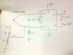
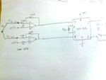
I'm trying to interface a thermocouple to microcontroller. As the thermocouple produces very low voltage, I've given an INA126P instrumentation amplifier to amplify the voltage. I'm using +5V as V+ and GND as V- and Vref=2.5V.
But, in the datasheet it says input common mode voltage is 1.5V to 3.5V (from graph). So, I tried to add an offset to the thermocouple input.
I've done that in two ways:1)Using an Op-amp and 2)Using a voltage divider.
here is my schematic........
1)Using voltage divider......

2)Using Opamp.....

Sorry, it's hand drawn....
May I know my circuit is correct?
Thank you
I'm trying to interface a thermocouple to microcontroller. As the thermocouple produces very low voltage, I've given an INA126P instrumentation amplifier to amplify the voltage. I'm using +5V as V+ and GND as V- and Vref=2.5V.
But, in the datasheet it says input common mode voltage is 1.5V to 3.5V (from graph). So, I tried to add an offset to the thermocouple input.
I've done that in two ways:1)Using an Op-amp and 2)Using a voltage divider.
here is my schematic........
1)Using voltage divider......

2)Using Opamp.....

Sorry, it's hand drawn....
May I know my circuit is correct?
Thank you