Continue to Site
Follow along with the video below to see how to install our site as a web app on your home screen.
Note: This feature may not be available in some browsers.
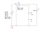
I would suggest you make your SWITCH on and off voltages within you operating range such as 2V and 3V not 0V and 5V. Also, check the ON and OFF resistances of the switch - by default they are 1 ohm and 1M ohm which may not be what you want.
Also, I am not sure what you are expecting. You have no discharge path so the capacitor will charge up to 5V and stay there.
Keith
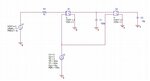
To duplicate that you need two switches in order to create a changeover switch. Set the two switched with opposite threshold voltages so one is on when the other is off. Alternatively you could use two different clocks, which would be necessary if you wanted to ensure they didn't overlap.
Keith