Continue to Site

Welcome to EDAboard.com

Welcome to our site! EDAboard.com is an international Electronics Discussion Forum focused on EDA software, circuits, schematics, books, theory, papers, asic, pld, 8051, DSP, Network, RF, Analog Design, PCB, Service Manuals... and a whole lot more! To participate you need to register. Registration is free. Click here to register now.

Electret Microphone preamp circuit interface for A2D

Status
Not open for further replies.

ha9981

Newbie level 4
Joined
Jan 11, 2013
Messages
7
Helped
0
Reputation
0
Reaction score
0
Trophy points
1,281
Activity points
1,356
I have the following Microphone: CZ034GU
Sensitivity -47 +- 4dB
Low Impedance
Current Consumption 500uA
Standard Operation Voltage 1.5V
S/N ratio more than 58dB

**broken link removed**

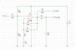
I have seen that to get this to input into any amplifier it needs Vin connected to output pin with a resistor followed by capacitor in series before input into the amplifier.

I found some sample circuits:
http://www.inexglobal.com/downloads/ZX-sound_e.pdf
http://fritzing.org/projects/electret-mic-opamp/
http://www.sparkfun.com/datasheets/BreakoutBoards/Amplified-Mic-Electret-v14.pdf

But I am still confused. I need to have a LPF as I will be using this to sample audio. It is to interface to microcontroller A2D. I need an output range of 0v to 5v, but what gain do I need I have no idea, I cannot find spec on microphone output range.

Where do I start?

here are some op-amps I found:
TLC272
LM386
TL071
OPA344

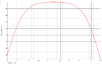
Also what is a good LPF filter for audio fc = 4khz because fs = 8khz.

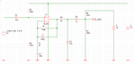
Here is some info I found on active LPF circuits.

I am in a bit of a hurry as electronics store for Op-Amp is only open saturday and then on tuesday. If you had to pick an op-amp for audio which would it be?
 

if you build the first part of the first attachment and take your output from IC 1/1 pin 1, you will have a X 100 amplifier. if this is not enough gain then replicate the component values and connections to IC1/2. i.e. pin 1 IC1/! goes to IC1/2 pin 6. This will give you an extra X100 gain, if this is too much (100 X 100 = 10,000) then replace the new R4 on IC1/2 with a variable resistor. if its value is 1 K then gain = X1, if 10K then gain = X10. For the output. Pin 7 IC1/2, will sit at 1/2 of the DC supply line and the signal will go + - about this. If you want proper AC then wire in C3, positive to Pin 7 , negative to a 10K to earth, take your output from across the 10 K.
Frank
 

Unfortunately the only IC OpAmps I was able to get were:
386N
358N
72ACP
74CN

Fortunately I can use 9V battery for PSU, so that helps.
I built this circuit which has 100gain, it is really noisy can hear sound but it is not clear. I doubt sampling such audio would be a good idea.

**broken link removed**

How should I attempt to improve it? Should I start with LPF first? Or change the IC for a better op-amp?
 

It seems the circuit is only providing output 200mv PK on loudest speech into microphone.

I guess the information on the microphone was wrong it is definitely not given anywhere near 50mV output. I tried with oscilloscope.

Anyone have an idea how to fix this? I tried putting another LM358 with gain 100, and gain 47 but didn't work to provide any better output
 

I think the 10K pullup is too low an impedance, you will end up
with a high pass characteristic. I've mostly seen the element
driving a JFET gate with much higher impedances.

Consider whether your problem is a lack of gain, or more a
surplus of noise.

Now a bare electret element ought to consume no power
at all, so maybe this is one with an active element inside
it, and unlike what I am remembering. The 500uA has to
go somewhere and the capacitive microphone element
is not it. If this is the case then polarity matters, but the
schematic indicates none.
 

LM358 is quite noisy, but if the microphone provides enough signal (>10 mV) it might be adequate. TL071 / TL072 are much better opamps, but need a higher voltage supply, like 12 V and the output should be capacitively coupled to the ADC pin, and the pin biased to VCC/2 with resistors.

The problem with the schematic you posted is the low input impedance, 1k -- because of the inverting configuration, thus loading the output impedance of the microphone.

Use the non-inverting configuration, with higher value input resistors, like in this schematic. Capacitors C3 and C4 provide a bit of low pass filtering.
Also, you may try to reduce electret microphone bias resistor to 4k7, or around this value.
 

Attachments

  • sch.png
    sch.png
    12.3 KB · Views: 179
  • gain.png
    gain.png
    25.1 KB · Views: 188
Last edited:

The old LM358 dual opamp is too noisy (hiss) to be a high gain mic preamp and it has crossover distortion.
I agree that the opamp should be non-inverting with a high input impedance so it does not load down the mic.
I have never seen an electret mic that works from only 1.5V, my mics are powered from 9V. How did you make 1.5V?
Your sampling frequency is very low so the lowpass filter must be sharp (complicated) or the cutoff frequency of a simple filter will cut most of the important consonant sounds of speech.
 

I used the circuit above with 9V and got the mic to power a small speaker. The intent was not to use a speaker but to do signal conditioning for ATD.

I changed the gain to 44 and biased the positive terminal of OpAmp at 2.6 V. I can get a signal out now that on DC reading from multimeter is 2.6V on no sound and from sound it shows on the oscilliscope the Pk to Pk is up to 3V. When I speak into Microphone the oscilloscope shows that circuit is functioning as the frequency changes in response to my voice. But the Vmin says it gets as low as -300mV which is an issue as it shouldn't go negative. Not sure what I am doing wrong. This is all with LM358.

My input impedance is 1kOhm, is that too low?

- - - Updated - - -

I managed to acquire TL071 but I only have 9V battery supply. Not sure how to get a 12V, how can I get one?

I think microphone is providing enough signal (>10mV) as it gets upto 5V pk-pk with my LM358 powered by 9V Vcc and 100 gain ratio of resistors (R5/R4). My oscilloscope may be too cheap to try to get a fair reading on the microphone alone, it is a digital <$200 oscilloscope.

Should I use your circuit with 9V supply, and then bias the A2D input at 2.5V using voltage divider?

I cannot seem to figure out your circuit design, not sure what is the gain. Will look into it further.

- - - Updated - - -

LM358 is quite noisy, but if the microphone provides enough signal (>10 mV) it might be adequate. TL071 / TL072 are much better opamps, but need a higher voltage supply, like 12 V and the output should be capacitively coupled to the ADC pin, and the pin biased to VCC/2 with resistors.

The problem with the schematic you posted is the low input impedance, 1k -- because of the inverting configuration, thus loading the output impedance of the microphone.

Use the non-inverting configuration, with higher value input resistors, like in this schematic. Capacitors C3 and C4 provide a bit of low pass filtering.
Also, you may try to reduce electret microphone bias resistor to 4k7, or around this value.

I am using 9V supply, I have TL071 IC but would need to get a 12V supply which is a challenge as I have no idea how get an affordable one.

My microphone seems to provide more than 10mV, I will try and verify, but question the capability of my digital oscilloscope.

I am confused about your proposed circuit, what is Vout? Isn't your circuit missing any capacitive coupling to ADC? How is the gain set? Doesn't seem to have higher input impedance.
 

The circuit posted recently is a normal non-inverting opamp with its (+) input biased at half the supply. The two 100k resistors set the input impedance at 50k ohms.
The negative feedback sets the gain at 101.

The output of the opamp cannot go negative when it does not have a negative supply voltage. With a 9V supply, the output of an LM358 can go very close to 0V and as high as 7.7V (which might destroy the A2D) when its load current is only 1mA.

The electret mic should feed a non-inverting opamp with an input impedance of 50k ohms as in this circuit.

The minimum supply for a TL071 is 7V but a little 9V battery quickly drops to less than 7V.
 

You can't connect directly a low impedance speaker to a low power opamp like LM358, because its current capability is very low.

With the schematic posted you should only use LM358 and a 5V supply, with a higher voltage you may destroy the ADC.

You can eliminate the output capacitor, C5, and only use the To_ADC output to connect to the ADC or probe with the oscilloscope in DC coupling mode. I had the impression you needed a secondary AC coupled output.

If you want to use TL071 with a 9V supply, it should be also biased at half voltage, 4.5V, to function correctly. Then the output should be AC coupled to the ADC input, that is separately biased at 2.5 V, using resistors R6 and R7. I recommend you don't eliminate R5, because it will reduce the inrush current applied to the ADC input (hopefully the ADC has internal clamping diodes) at power-up when C5 is discharged.
 

Attachments

  • tl071_adc.png
    tl071_adc.png
    14.1 KB · Views: 147
  • signal.png
    signal.png
    27.3 KB · Views: 148
  • Like
Reactions: ha9981

    ha9981

    Points: 2
    Helpful Answer Positive Rating
You can't connect directly a low impedance speaker to a low power opamp like LM358, because its current capability is very low.

With the schematic posted you should only use LM358 and a 5V supply, with a higher voltage you may destroy the ADC.

You can eliminate the output capacitor, C5, and only use the To_ADC output to connect to the ADC or probe with the oscilloscope in DC coupling mode. I had the impression you needed a secondary AC coupled output.

If you want to use TL071 with a 9V supply, it should be also biased at half voltage, 4.5V, to function correctly. Then the output should be AC coupled to the ADC input, that is separately biased at 2.5 V, using resistors R6 and R7. I recommend you don't eliminate R5, because it will reduce the inrush current applied to the ADC input (hopefully the ADC has internal clamping diodes) at power-up when C5 is discharged.

Since the ADC is in the microprocessor I think I will avoid the 9V supply as I am guessing TL071 is rail-to-rail and can possibly destroy ADC in my microprocessor chip. I will first try with LM358 circuit you suggested on 5V supply and see where I can get. If that doesn't work out well I will fall back to TL071 with 9V to power IC and 5V to bias ADC input to 2.5V. I am curious how gain is set on the TL071 circuit you proposed.

Currently the plan is to use 5V supply on my initial LM358 design I found online as posted above and bias the output at 2.5V to see how it performs. Hopefully I can get it to swing decently as long as it doesn't manage to get past 5V and blow the ADC.

Initially my LM358 design is working as of now on 9V but the issue is that it still manages to go negative range which is really annoying. I will do some more experimenting by Wednesday or Thursday and get back to you guys.

THANKS A MILLION.
 

I am guessing TL071 is rail-to-rail
Don't guess, look on its datasheet. It is too old to be rail-to-rail.
With a 9V supply its output goes high to about +7.5V and goes low to about +0.9V. Then its max output swing is 6.6V p-p which will destroy your ADC.

I am curious how gain is set on the TL071 circuit you proposed.
The same as any other non-inverting opamp circuit. The gain is (R2/R1) +1= 101 times. R2 and R1 provide negative feedback.

Currently the plan is to use 5V supply on my initial LM358 design I found online as posted above and bias the output at 2.5V to see how it performs. Hopefully I can get it to swing decently as long as it doesn't manage to get past 5V and blow the ADC.
Some of the schematics you found WILL NOT WORK! The first one produces only a DC pulse when there is a sound.

Connect one opamp of an LM358 exactly the same as the TL071 circuit. With a 5V supply its output goes high to about +3.7V and goes low to about +0.1V.
 

Status
Not open for further replies.

Similar threads

Part and Inventory Search

Welcome to EDABoard.com

Sponsor

Back
Top