Continue to Site

Welcome to EDAboard.com

Welcome to our site! EDAboard.com is an international Electronics Discussion Forum focused on EDA software, circuits, schematics, books, theory, papers, asic, pld, 8051, DSP, Network, RF, Analog Design, PCB, Service Manuals... and a whole lot more! To participate you need to register. Registration is free. Click here to register now.

Current limit with constant voltage

Status
Not open for further replies.

Cval

Junior Member level 1
Joined
Jan 23, 2012
Messages
19
Helped
0
Reputation
0
Reaction score
0
Trophy points
1,281
Activity points
1,442
I am currently working on a project that requires some sort of current limiting circuit with minimized voltage drop. I have a 9V battery powering an electric motor that spins a wire. I want to limit the current draw to approx 0.5A, otherwise the wire over-torques and can break. I can’t change the motor or battery. Essentially I am trying to create an electric clutch that will “slip” or hold at a peak current I can specify (somewhere between 0.35-0.8A). Space is limited inside the housing.
The closest to what I am looking for is https://www.onsemi.com/pub_link/Collateral/NCP380-D.PDF but this is rated for a 5V Vin. I am a mechanical engineer by trade, so I’m a bit out of my element here. Any help would be appreciated.
 

Why not to connect a resistance in series between the battery and the motor. You can connect a 50 ohm potentiometer and tune it to your desired current. Voltage drop will be negligible, as v is directly proportional to I. to need 0.5A, you need 18 ohm....
 

Below is a current-limit circuit using four components. The drop across R2 is about 0.65V at the limit. R2 can be changed to get the limit you want. The P-MOSFET can be any device with at least a 20V and 1A rating. If the limit may be occurring for a long time period than you need to consider a heat-sink for the MOSFET.

Current Limit.gif
 
  • Like
Reactions: Cval

    Cval

    Points: 2
    Helpful Answer Positive Rating
Below is a current-limit circuit using four components. The drop across R2 is about 0.65V at the limit. R2 can be changed to get the limit you want. The P-MOSFET can be any device with at least a 20V and 1A rating. If the limit may be occurring for a long time period than you need to consider a heat-sink for the MOSFET.

View attachment 87965


I am trying to understand what's happening in this circuit. The current passed R2 controls the PNP gate to open/close, this then determines whether enough voltage is present to open the PMOS which is then supplied to the motor, otherwise it's pushed to R1? I'm still a bit confused on what exactly is going on throughout the circuit.

What is the mathematical relationship between R2 and the max allowable current?
 

At low current the PNP transistor is off. The P-MOSFET M1 gate is connected to ground through R1 so the MOSFET is fully ON (Vgate is 9V negative with respect to the MOSFET source). When the current increases to where the voltage drop across R2 reaches about 0.65V, Q1 starts to turn on and current flows through R1. This increases the voltage across R1 which reduces Vgs. This causes M1 to start turning off when it gets near its Vgs threshold voltage, limiting the current to that level.

The current limit point is thus about .65V / R2 or 0.5A.

Note that the convention for transistors is they are ON or OFF, not closed or open (which is a relay term). ;-)
 
  • Like
Reactions: Cval

    Cval

    Points: 2
    Helpful Answer Positive Rating
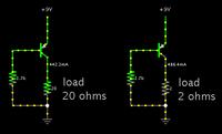
You may find a single transistor is sufficient to limit current.

The schematics below are identical except for the load.

That circuit depends upon the beta value of the transistor to determine the current limit. This gives a large variation in the limit from transistor to transistor due to the wide manufacturing variation in beta. Thus the base resistor would have to be selected for the particular transistor you are using.
 

That circuit depends upon the beta value of the transistor to determine the current limit. This gives a large variation in the limit from transistor to transistor due to the wide manufacturing variation in beta. Thus the base resistor would have to be selected for the particular transistor you are using.

Yes, I should have made it a potentiometer instead. That would convey the need to tailor-adjust the ohm value.

It will need to be adjusted if you might have different supply voltages.
A new 9V battery can be higher than 9V.
A rechargeable 9V might really put out 7.2 V (older type containing 6 cells), or 8.4 V (containing 7 cells). A lower supply V will result in less current to the load.
 

Yes, I should have made it a potentiometer instead. That would convey the need to tailor-adjust the ohm value.
Power dissipation in your circuit is approximately 2V * 0.5A = 1W. Need a radiator for Q1 and remain problems with the thermal stability.
It will need to be adjusted if you might have different supply voltages.
A new 9V battery can be higher than 9V.
A rechargeable 9V might really put out 7.2 V (older type containing 6 cells), or 8.4 V (containing 7 cells). A lower supply V will result in less current to the load.
Changing the battery voltage if too low, requires an adjustment of the base current. Necessary to use a current source to stabilize the base current.

I believe that the circuit shown crutschow better.
 

Thanks for all your help, I've ordered the components, we'll see how testing goes.
 

Everything worked great, there was some speed drop, but not as bad as the resistor we were using. The p-mosfet does get very hot (smoking) with stalls longer than ~10 seconds.
 

Everything worked great, there was some speed drop, but not as bad as the resistor we were using. The p-mosfet does get very hot (smoking) with stalls longer than ~10 seconds.
That's by nature of the circuit. It either needs a sufficient transistor heatsink or a mechanism to shutdown the output current after a delay.
 

Below is a current-limit circuit using four components. The drop across R2 is about 0.65V at the limit. R2 can be changed to get the limit you want. The P-MOSFET can be any device with at least a 20V and 1A rating. If the limit may be occurring for a long time period than you need to consider a heat-sink for the MOSFET.

View attachment 87965

This circuit has been working well, but I have a few questions. What attributes should I look for in a P-MOSFET so that I have as little voltage drop as possible when it's on, is that the Rds value? Also, we are using alkaline 9V batteries and we are seeing a non-linear drop in voltage over time. Would it be possible to add a voltage regulator so that a constant voltage is drawn from the batteries. (For example, a flashlight that slowly starts to dim over time vs. a flashlight that stays bright, but suddenly dies). This would likely reduce battery life over time, but that's not an issue. I was considering a DC-DC voltage regulating PMIC or something similar. We also can't use lithium because of disposal issues.

Thanks!
 

Yes, the Rds value determines the voltage drop when the MOSFET is fully on.

You could use a low-dropout linear regulator to regulate the voltage but that will waste some power. A switching regulator would have higher efficiency.

Using 6 alkaline C or D cells in series will last a lot longer than a 9V battery.
 

At low current the PNP transistor is off. The P-MOSFET M1 gate is connected to ground through R1 so the MOSFET is fully ON (Vgate is 9V negative with respect to the MOSFET source). When the current increases to where the voltage drop across R2 reaches about 0.65V, Q1 starts to turn on and current flows through R1. This increases the voltage across R1 which reduces Vgs. This causes M1 to start turning off when it gets near its Vgs threshold voltage, limiting the current to that level.

The current limit point is thus about .65V / R2 or 0.5A.

Note that the convention for transistors is they are ON or OFF, not closed or open (which is a relay term). ;-)

Another question, where did 0.65V come from? I understand that V=I(stall)*1.3 = 0.65, but then you would have needed to know the R value first.
 

Another question, where did 0.65V come from? I understand that V=I(stall)*1.3 = 0.65, but then you would have needed to know the R value first.

Think of it as a constant value (base emitter voltage drop)
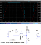
You can reduce the loss by applying a more complicated setup, but overloaded motor current limit 1.5A power dissipation remains at 11W and if you do not want it, you have to apply additional logic in the circuit to avoid that.Isource.pngIsourceW.png
 

Status
Not open for further replies.

Similar threads

Part and Inventory Search

Welcome to EDABoard.com

Sponsor

Back
Top