Continue to Site

Welcome to EDAboard.com

Welcome to our site! EDAboard.com is an international Electronics Discussion Forum focused on EDA software, circuits, schematics, books, theory, papers, asic, pld, 8051, DSP, Network, RF, Analog Design, PCB, Service Manuals... and a whole lot more! To participate you need to register. Registration is free. Click here to register now.

Current clamp with reference

cupoftea

Advanced Member level 5
Joined
Jun 13, 2021
Messages
2,611
Helped
54
Reputation
108
Reaction score
115
Trophy points
63
Activity points
13,685

Attachments

  • Current clamp with reference.jpg
    Current clamp with reference.jpg
    145.3 KB · Views: 57
  • Current clamp LM4041DYM3_1p2.zip
    1.1 KB · Views: 56
Hi,
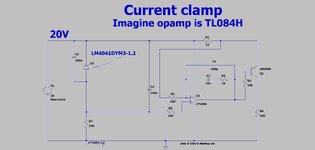
The attached current clamp uses the LM4041DYM3-1.2 as a reference. (jpeg and LTspice as attached)
Our contractor says that the two 100nF caps on this reference will make it unstable.
But the LM4041DYM3-1.2 datasheet says it "tolerates capacitive loads".
So do you agree, it will be fine?

LM4041DYM3-1.2
Since it states "tolerates" C loads, but gives no limit, I would contact vendor
FAE or tech support for what that means exactly. Datasheet does show Z graphs
with 1 uF load, but thats still nebulus, a ceramic or a electrolytic, no ESR discussion,
blah blah blah.

Contact the vendor.


Regards, Dana.
 
I agree with your contractor. But if you use what they do, it shows the Zo plot with high Q to be max at ~ 10 kHz with 1uF Tantalum where Zo ~ 0.3 Ohms nom at DC.

So you want the real part of load much higher than Zout for high phase margin with an emitter follower load especially in a closed loop.

1 uF Tantalums range from 2 to 20 Ohms. So if you used 0.1 uF out then add 10 ~ 100 ohms in series with cap for best phase marginj , but noise suppression suffers.

I'd drop the output cap and enjoy the free white noise.

LM4040/LM4041
DS20005757B-page 14 2017-2018 Microchip Technology Inc.
Wideband Noise eN — 20 — μV RMS

1704297441557.png
 
Last edited:
and they are in parallel, is that a mistake on the schematic or something to do with decoupling?
Thanks, the LM4041 is some 7cm away from the opamp on the PCB...so there's one 100nF near the LM4041, and one parallel to it, but near the opamp.
 
Interestingly, it was well stable with either 100n, 200n, 300n, 1u or 11u.
I never saw any instability with it.
The above are all MLCC, except the 11u which was (10u SMD Tant + 1u MLCC)

I believe this reference is pretty well unconditionally stable with capacitance.
The reference as such is not actually "loaded" resistively at all.
 

LaTeX Commands Quick-Menu:

Similar threads

Part and Inventory Search

Welcome to EDABoard.com

Sponsor

Back
Top