Continue to Site

Welcome to EDAboard.com

Welcome to our site! EDAboard.com is an international Electronics Discussion Forum focused on EDA software, circuits, schematics, books, theory, papers, asic, pld, 8051, DSP, Network, RF, Analog Design, PCB, Service Manuals... and a whole lot more! To participate you need to register. Registration is free. Click here to register now.

What is the 555 configured as in this schematic?

Status
Not open for further replies.

boylesg

Advanced Member level 4
Joined
Jul 15, 2012
Messages
1,023
Helped
5
Reputation
10
Reaction score
6
Trophy points
1,318
Location
Epping, Victoria, Australia
Activity points
11,697
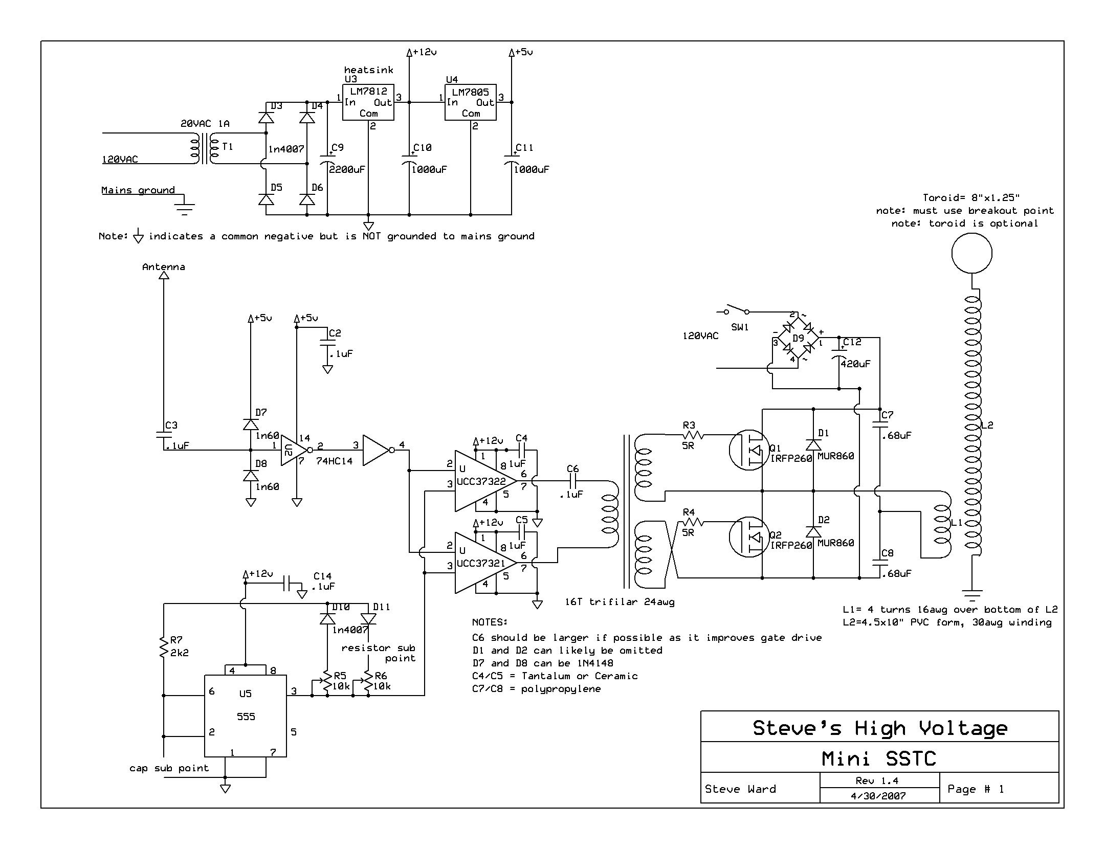
It is clearly not a standard astable multivibrator.

Does nayone recognize this configuration?

I would like to understand it better.

miniSSTCfnlsch.JPG
 

It's unusual but I think it's an astable circuit with R5 and R6 providing control over the output on/off periods is what it is intended to do. The 'sub' points are where capacitors and resistor may have to be 'substituted' to get the frequency and output right. I would think the more conventional circuit would work better. The input to U2 is also floating which is asking for trouble!

If you build it, note that the FETs are not isolated from the mains power and are rated for 120V AC input, if you are in a 230V country you will need higher rated devices.

Brian.
 

I don't agree about "unusual". A 555 circuit with feedback from output instead of DISCHG pin can be already found as 50 % duty cycle oscillator in the LMC555 datasheet. The variant with diodes and variable duty cycle is at least frequently used.
 

I don't agree about "unusual". A 555 circuit with feedback from output instead of DISCHG pin can be already found as 50 % duty cycle oscillator in the LMC555 datasheet. The variant with diodes and variable duty cycle is at least frequently used.

OK. Well I need to consult a datasheet rather than the websites I was consulting about 555 circuits. I have not come across this type of 555 configuration in them.

What is the advanrtage of taking feedback from the output pin rather than the discharge pin if any?
 

The advantage of the said 50% duty cycle circuit is mnimum part count. It should be noted, that the 50% feature depends on CMOS 555 type and only light output load. All in all it's just another circuit option you can play with when designing circuits.
 

The 'output' and 'discharge' pins carry identical signals but have different electrical characteristics so it is posible to swap them in some circumstances.

I agree with FvM that some flavors of 555 are different to others, the worst case of this I found was a type that 'froze' it's ouput when reset was applied rather than turning the output off. It caused me considerable problems once in a HV power unit where it fed the gate of a MOSFET in an inverter which had it's output fed back to the reset pin to give crude voltage stabilization (it was a pre-regulator circuit). Instead of shutting the FET off when the output voltage was reached, it randomly left it turned on and drew enough current to overheat it. I can't remember the manufacturer but in most 555s the reset pin directly connects to the output flip-flop, in this one it gated the input to it instead.

Brian.

Well, as I understand it, the purpose of the 555 ciruit is to enable the mosfet gate drivers at a given frequency and on time so as to control the current going through the primary coil. The longer the on time the larger the resonant current will reach in the primary coil, possibly to the point of blowing the mosfets.

So I can't see any reason why it couldn't be a standard astable or extended duty cycle astable arrangement. I could use a pot as R1 or R2 to vary the duty cycle and use a 8 pin dip socket to change timing capacitors both on the fly.

I also note that in the 555 specs you can use an standard 555 monostable arrangement, triggered with a continuous pulse stream from the above astable arrangement for example, as a pulse width modulator, with audio signal input to pin 5 of the monstable 555. I might get better sound through the arcs with this method as opposed to puting the audio signal into pin 5 of an astable 555 arrangement as I have done with the flyback transformer driver.
 

What puzzles me is why two potentiometers are used. Their relative values change the on/off ratio and their combined values set the frequency (as well as the 'sub' capacitor). Personally, I would have gone for a more conventional astable circuit where the frequency and ratio are less dependant on each other. I'm also a little puzzled by the antenna circuit. If I understand it, the 555 does not set the output frequency, that is decided by the feedback, presumably from the arc to the antenna which I'm guessing is primarily controlled by the inductance of the output transformer. The 555 is there either to allow some degree of control over it, or to provide the initial 'kick' to start it running.

I'm also puzzled as to why two high current FET drivers are used to drive a transformer, I would think it makes more sense to drive the FETs directly as the output is isolated anyway. I can see the potential mains power isolation issue. Also, why use an inverting and a non-inverting FET driver when their inputs come from an inverter where both polarities are available anyway. It isn't wrong as it is, just curiously designed.

Brian.

If you read is description of this circuit he originally had another 555 circuit that was designed to kick start the oscillations, but he found that the oscillations started wothout the second 555 installed. Apparently the inverting gate driver sends out a first pulse that turns one of the mosfets on and kick starts the oscillations.

So in the final iteration of his circuit he removed that second 555 circuit.

As I understand his description, the last 555 circuit is there to control the on time for the resonant oscillations between the primary and secomdary coils.

This changes the nature of the arcs and also determines the peak resonant current that flows through the primary coil and the mosfets.

He has apparently blown mosfets by allowing this resonant current to exceed the current rating or the power rating of the mosfets or igbts he was using......as I understand it.

- - - Updated - - -

I'm also puzzled as to why two high current FET drivers are used to drive a transformer, I would think it makes more sense to drive the FETs directly as the output is isolated anyway. I can see the potential mains power isolation issue. Also, why use an inverting and a non-inverting FET driver when their inputs come from an inverter where both polarities are available anyway. It isn't wrong as it is, just curiously designed.

Brian.

If the fets failed you could potentially get 120V leaking back into the low voltage circuitry couldn't you?

That is why he says he uses the gate driver transformer to couple the gate driver ICs to the fets - so there is no direct electrical connection.

Even if you have both polarities available, how else would you be able to turn the fets on and off given that it is best to use gate driver ICs.

Both flavours of gate driver IC respond oppositely to a positive voltage signal.
 

I understand the implications of damage if the FETs die but the vast majority of inverters and FET power switches used direct drive without any problems and using the driver transformer like that increases costs and reduces efficiency. In fact, direct drive to the FETs probably makes them more reliable than using a transformer anyway. My point about the driver ICs is simply that it seems odd (but not wrong) to use two different drivers when the signal feeding them comes from an inverter IC anyway. It usually works out cheaper to use the same IC type and feed the inputs from pins 3 & 4 of the 74HC14 feeding it.

Brian.

Well in that case I might just try it without the gate driver transformer at some point.

I guess the first step would be to establish what sort of resonant current I am getting through the primary coil and see if the 800V/25A power FETS are up to the challenge. Voltage rating should be way more than enough but the current rating is half that of the FETs specied by Steve Ward.

I have accumulated a fair few fuses of various values from old TVs. I was thinking of puting these in parallel to various larger values and then puting these in series with the primary coil and see if they blow. It shouldn't be too hard to figure out what sort of peak current I am getting. The FETS specified by steve ward are only 200V ones so 250V fuse should be fine.

I was toying with the idea of accumulating 10 x car batteries to do this. It is a bit of a pain but I am still reluctant to plug this sort of thing into the mains.

Can you suggest the best way to protect the low voltage circuitry from any HV strike to the antenna?

Steve Ward mentions that one such strike did indeed destroy his drive circuit and I would like to avoid this if possible.
 
Last edited:

Putting fuses in parallel isn't a good way to test for current! A far better way is to place a low value resistor (suggest 0.1 Ohm) in series with the supply and measure the voltage across it, preferably with an oscilloscope.

Bear in mind that the average FET current is being drawn from your mains supply. I'm not sure where you are but it's rare for a wall outlet to be rated at 25A so something else will likely blow before the FETs or fuses.

I'm not convinced an antenna is the best way to do this but given the high impeadance at the HC14 input pin, I would suggest putting a resistor of say 10K in series with the antenna. Keep the two diodes on the IC side of the resistor. The classic protection method would be to wire a neon lamp between the antenna wire and ground as well. It will do nothing until about 90V is across it then it will flash and conduct the HV away.

Brian.

Any particular type of neon lamp Brian?

I have some small neon tubes that I removed from a battery operated camping lamp. Would you suggest that these are adequate for the purpose?

- - - Updated - - -

Putting fuses in parallel isn't a good way to test for current! A far better way is to place a low value resistor (suggest 0.1 Ohm) in series with the supply and measure the voltage across it, preferably with an oscilloscope.

Bear in mind that the average FET current is being drawn from your mains supply. I'm not sure where you are but it's rare for a wall outlet to be rated at 25A so something else will likely blow before the FETs or fuses.
Brian.

Nah! I am not going to power it from a wall socket Brian. I am too afraid I will end up burning down the house.

I have just acquired 6 more car batteries from a local disused car junkyard. So I now have 108V once I recharge them all and I don't have to frig around with bridge rectifiers etc.

It's is a pain storing, moving and recharging them all but it is a great deal safer re the house.

I know from my flyback driver that the fixed 3W to 20W resistors wont withstand the high current this thing is likely to draw - they tend to burn out rather quickly.

I do have some nichrome wire I salvaged from a discarded heater. I am currently using a length of this as my current limiting resistor for my flyback driver and it works brilliantly as long as you don't touch it.

I can use the same method to measure the current in the tesla primary as you suggest.
 

I've never heard of neon lamps being used in a camping lamp before so I can't comment on that. The type you want are small glass tubes, about 10mm long and 5mm diameter with two wires leaving at one end. Inside you can see two parallel electrodes which glow orange when it's lit up. They are commonly used as power indicators in wall sockets or on some mains powered appliances, connected across the AC with a series resistor of 150K or so to limit their current. Electrically, because the electrodes don't touch and neon gas isn't conductive, they are open circuits and as such will have no effect on the antenna signal whatsoever. The way they protect is to do with a property of neon gas that allows it to ionize easily. When the voltage across the electrodes reaches 'striking' voltage, which is usually around 100V, the gas ionizes and starts to conduct, in this state it looks electrically like a low value resistor and will conduct considerable current if allowed to do so. That's why the high value resistor is used in an AC indicator application, without it the neon would explode violently.

If you put one from the antenna to ground it will do nothing unless the antenna voltage reaches 100V or so and at that point, it will flash and safely (I hope!) short the current safely to ground. The 10K resistor I suggested will limit the current toward the IC to a level the two diodes can safely carry and dump either to ground or the supply rail.

Nichrome isn't a good material for making resistors. It has a high temperature coefficient, meaning it's value changes significantly with temperature. You can use it but to work out the current using I = V/R you need to know what R actually is and while hot the value will be difficult to measure. The current will be in pulses anyway which makes it even more complicated to measure, that's why I suggested an oscilloscope which lets you see and measure the peaks and dips of curent in real time.

Brian.
 

Regarding the gate driver transformer.....

What about if you were to place an appropriate quick blow fuse between the mosfet gate driver IC and the mosfet gate?

That way if the mosfet failed and 108V went through to the low voltage circuitry it would blow the fuse, hopefully before it damaged the gate driver IC.
 

It's worth a try. The gate driver can handle 9A peak and the gate current will be mostly dynamic currents and much smaller so you can probably use 1A fuse or even less. Make sure it's a "fast blow" type and not "anti-surge". You could add extra protection by adding a Zener diode from the drive signal to ground on the IC side.

Brian.
 

I've never heard of neon lamps being used in a camping lamp before so I can't comment on that. The type you want are small glass tubes, about 10mm long and 5mm diameter with two wires leaving at one end. Inside you can see two parallel electrodes which glow orange when it's lit up. They are commonly used as power indicators in wall sockets or on some mains powered appliances, connected across the AC with a series resistor of 150K or so to limit their current. Electrically, because the electrodes don't touch and neon gas isn't conductive, they are open circuits and as such will have no effect on the antenna signal whatsoever. The way they protect is to do with a property of neon gas that allows it to ionize easily. When the voltage across the electrodes reaches 'striking' voltage, which is usually around 100V, the gas ionizes and starts to conduct, in this state it looks electrically like a low value resistor and will conduct considerable current if allowed to do so. That's why the high value resistor is used in an AC indicator application, without it the neon would explode violently.

If you put one from the antenna to ground it will do nothing unless the antenna voltage reaches 100V or so and at that point, it will flash and safely (I hope!) short the current safely to ground. The 10K resistor I suggested will limit the current toward the IC to a level the two diodes can safely carry and dump either to ground or the supply rail.

Nichrome isn't a good material for making resistors. It has a high temperature coefficient, meaning it's value changes significantly with temperature. You can use it but to work out the current using I = V/R you need to know what R actually is and while hot the value will be difficult to measure. The current will be in pulses anyway which makes it even more complicated to measure, that's why I suggested an oscilloscope which lets you see and measure the peaks and dips of curent in real time.

Brian.

With the antenna protection, neon bulb (I realised that is what you meant after I posted about the camping light neon tubes) in place how would you suggest I test the aerial circuitry to make sure the 10k resistor does not limit the normal current too much.

I was thinking I may have to implement a common collector amplifier if it limits the signal current too much.

Perhaps the RF from a mobile phone held close to the antenna? Anything else that would approximate the RF from a tesla coil?
 

Status
Not open for further replies.

Part and Inventory Search

Welcome to EDABoard.com

Sponsor

Back
Top